NETWORKING
ARP Overview
Address Resolution Protocol (ARP) is a protocol for mapping an Internet Protocol address (IP address) to a physical machine address, also known as a Media Access Control or MAC address, on the local area network.
An IP (version 4) address is 32 bits long. In an Ethernet LAN, MAC addresses are 48 bits long. The ARP table maintains an association between each MAC address and its corresponding IP address.
What You Need to Know
Read on for concepts on ARP that can help you configure the screen in this chapter.
How ARP Works
When an incoming packet destined for a host device on a local area network arrives at the Switch, the Switch looks in the ARP Table and if it finds the address, it sends it to the device.
If no entry is found for the IP address, ARP broadcasts the request to all the devices on the LAN. The Switch fills in its own MAC and IP address in the sender address fields, and puts the known IP address of the target in the target IP address field. In addition, the Switch puts all ones in the target MAC field (FF.FF.FF.FF.FF.FF is the Ethernet broadcast address). The replying device (which is either the IP address of the device being sought or the router that knows the way) replaces the broadcast address with the target's MAC address, swaps the sender and target pairs, and unicasts the answer directly back to the requesting machine. ARP updates the ARP Table for future reference and then sends the packet to the MAC address that replied.
ARP Learning Mode
The Switch supports three ARP learning modes: ARP-Reply, Gratuitous-ARP, and ARP-Request.
ARP-Reply
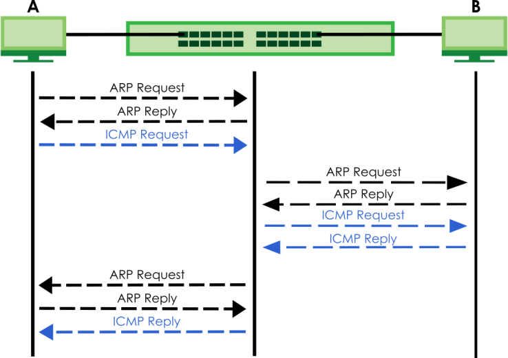
The Switch in ARP-Reply learning mode updates the ARP table only with the ARP replies to the ARP requests sent by the Switch. This can help prevent ARP spoofing.
In the following example, the Switch does not have IP address and MAC address mapping information for hosts A and B in its ARP table, and host A wants to ping host B. Host A sends an ARP request to the Switch and then sends an ICMP request after getting the ARP reply from the Switch. The Switch finds no matched entry for host B in the ARP table and broadcasts the ARP request to all the devices on the LAN. When the Switch receives the ARP reply from host B, it updates its ARP table and also forwards host A’s ICMP request to host B. After the Switch gets the ICMP reply from host B, it sends out an ARP request to get host A’s MAC address and updates the ARP table with host A’s ARP reply. The Switch then can forward host B’s ICMP reply to host A.
Gratuitous-ARP
A gratuitous ARP is an ARP request in which both the source and destination IP address fields are set to the IP address of the device that sends this request and the destination MAC address field is set to the broadcast address. There will be no reply to a gratuitous ARP request.
A device may send a gratuitous ARP packet to detect IP collisions. If a device restarts or its MAC address is changed, it can also use gratuitous ARP to inform other devices in the same network to update their ARP table with the new mapping information.
In Gratuitous-ARP learning mode, the Switch updates its ARP table with either an ARP reply or a gratuitous ARP request.
ARP-Request
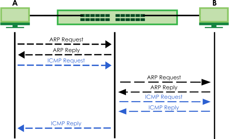
When the Switch is in ARP-Request learning mode, it updates the ARP table with both ARP replies, gratuitous ARP requests and ARP requests.
Therefore in the following example, the Switch can learn host A’s MAC address from the ARP request sent by host A. The Switch then forwards host B’s ICMP reply to host A right after getting host B’s MAC address and ICMP reply.
ARP Learning
Use this screen to configure each port’s ARP learning mode.
The following table describes the labels in this screen.
label | description |
|---|---|
Port | This field displays the port number. |
* | Settings in this row apply to all ports. Use this row only if you want to make some settings the same for all ports. Use this row first to set the common settings and then make adjustments on a port-by-port basis. Changes in this row are copied to all the ports as soon as you make them. |
ARP Learning Mode | Select the ARP learning mode the Switch uses on the port. Select ARP-Reply to have the Switch update the ARP table only with the ARP replies to the ARP requests sent by the Switch. Select Gratuitous-ARP to have the Switch update its ARP table with either an ARP reply or a gratuitous ARP request. Select ARP-Request to have the Switch update the ARP table with both ARP replies, gratuitous ARP requests and ARP requests. |
Apply | Click Apply to save your changes to the Switch’s run-time memory. The Switch loses these changes if it is turned off or loses power, so use the Save link on the top navigation panel to save your changes to the non-volatile memory when you are done configuring. |
Cancel | Click Cancel to begin configuring this screen afresh. |
DHCP Overview
DHCP (Dynamic Host Configuration Protocol RFC 2131 and RFC 2132) allows individual computers to obtain TCP/IP configuration at start-up from a server. If you configure the Switch as a DHCP relay agent, then the Switch forwards DHCP requests to DHCP server on your network. If you do not configure the Switch as a DHCP relay agent then you must have a DHCP server in the broadcast domain of the client computers or else the client computers must be configured manually.
DHCP Modes
If there is already a DHCP server on your network, then you can configure the Switch as a DHCP relay agent. When the Switch receives a request from a computer on your network, it contacts the DHCP server for the necessary IP information, and then relays the assigned information back to the computer.
DHCPv4 Configuration Options
The DHCPv4 configuration on the Switch is divided into Smart Relay and VLAN screens. The screen you should use for configuration depends on the DHCP services you want to offer the DHCP clients on your network. Choose the configuration screen based on the following criteria:
• Smart Relay – The Switch forwards all DHCP requests to the same DHCP server.
• VLAN – The Switch is configured on a VLAN by VLAN basis. The Switch can be configured to relay DHCP requests to different DHCP servers for clients in different VLAN.
DHCPv4 Relay Status
The following table describes the labels in this screen.
label | description |
|---|---|
Relay Mode | This field displays: None – if the Switch is not configured as a DHCP relay agent. Smart– if the Switch is configured as a DHCP relay agent only. VLAN – followed by a VLAN ID or multiple VLAN IDs if it is configured as a relay agent for specific VLANs. |
DHCPv4 Relay
Configure DHCP relay on the Switch if the DHCP clients and the DHCP server are not in the same broadcast domain. During the initial IP address leasing, the Switch helps to relay network information (such as the IP address and subnet mask) between a DHCP client and a DHCP server. Once the DHCP client obtains an IP address and can connect to the network, network information renewal is done between the DHCP client and the DHCP server without the help of the Switch.
The Switch can be configured as a global DHCP relay. This means that the Switch forwards all DHCP requests from all domains to the same DHCP server. You can also configure the Switch to relay DHCP information based on the VLAN membership of the DHCP clients.
DHCPv4 Relay Agent Information
The Switch can add information about the source of client DHCP requests that it relays to a DHCP server by adding Relay Agent Information. This helps provide authentication about the source of the requests. The DHCP server can then provide an IP address based on this information. Please refer to RFC 3046 for more details.
The DHCP Relay Agent Information feature adds an Agent Information field (also known as the Option 82 field) to DHCP requests. The Option 82 field is in the DHCP headers of client DHCP request frames that the Switch relays to a DHCP server.
DHCPv4 Option 82 Profile
Use this screen to view and configure DHCPv4 option 82 profiles.
The following table describes the labels in this screen.
label | description |
|---|---|
Profile Name | This field displays the descriptive name of the profile. |
Circuit-ID | This section displays the Circuit ID sub-option including information that is specific to the relay agent (the Switch). |
Enable | This field displays whether the Circuit ID sub-option is added to client DHCP requests. |
Field | This field displays the information that is included in the Circuit ID sub-option. |
Remote-ID | This section displays the Remote ID sub-option including information that identifies the relay agent (the Switch). |
Enable | This field displays whether the Remote ID sub-option is added to client DHCP requests. |
Field | This field displays the information that is included in the Remote ID sub-option. |
Select an entry’s checkbox to select a specific entry. Otherwise, select the checkbox in the table heading row to select all entries. | |
Add/Edit | Click Add/Edit to add a new entry or edit a selected one. |
Delete | Click Delete to remove the selected entries. |
Add/Edit a DHCPv4 Option 82 Profile
Use this screen to create DHCPv4 option 82 profiles. Click Add/Edit, or select an entry and click Add/Edit in the NETWORKING > DHCP > DHCPv4 Relay > DHCP Option 82 Profile link to display this screen.
The following table describes the labels in this screen.
label | description |
|---|---|
Name | Enter a descriptive name for the profile for identification purposes. You can use up to 32 printable ASCII characters. |
Circuit-ID | Use this section to configure the Circuit ID sub-option to include information that is specific to the relay agent (the Switch). |
Enable | Select this option to have the Switch add the Circuit ID sub-option to client DHCP requests that it relays to a DHCP server. |
slot-port | Select this option to have the Switch add the number of port that the DHCP client is connected to. |
vlan | Select this option to have the Switch add the ID of VLAN which the port belongs to. |
hostname | This is the system name you configure in the SYSTEM > General Setup > General Setup screen. Select this option for the Switch to add the system name to the client DHCP requests that it relays to a DHCP server. |
string | Enter a string of up to 64 printable ASCII characters that the Switch adds into the client DHCP requests. |
Remote-ID | Use this section to configure the Remote ID sub-option to include information that identifies the relay agent (the Switch). |
Enable | Select this option to have the Switch append the Remote ID sub-option to the option 82 field of DHCP requests. |
mac | Select this option to have the Switch add its MAC address to the client DHCP requests that it relays to a DHCP server. |
string | Enter a string of up to 64 printable ASCII characters for the remote ID information in this field. |
Apply | Click Apply to save your changes to the Switch’s run-time memory. The Switch loses these changes if it is turned off or loses power, so use the Save link on the top navigation panel to save your changes to the non-volatile memory when you are done configuring. |
Clear | Click Clear to clear the fields to the factory defaults. |
Cancel | Click Cancel to not save the configuration you make and return to the last screen. |
DHCPv4 Smart Relay
Use this screen to configure global DHCPv4 relay.
The following table describes the labels in this screen.
label | description |
|---|---|
DHCP Smart Relay | |
Active | Select this checkbox to enable DHCPv4 relay. |
Remote DHCP Server 1 .. 3 | Enter the IP address of a DHCPv4 server in dotted decimal notation. |
Option 82 Profile | Select a pre-defined DHCPv4 option 82 profile that the Switch applies to all ports. The Switch adds the Circuit ID sub-option and/or Remote ID sub-option specified in the profile to DHCP requests that it relays to a DHCP server |
Apply | Click Apply to save your changes to the Switch’s run-time memory. The Switch loses these changes if it is turned off or loses power, so use the Save link on the top navigation panel to save your changes to the non-volatile memory when you are done configuring. |
Cancel | Click Cancel to begin configuring this screen afresh. |
Port Use this section to apply a different DHCP option 82 profile to certain ports on the Switch. | |
Index | This field displays a sequential number for each entry. |
Port | This field displays the ports to which the Switch applies the settings. |
Profile Name | This field displays the DHCP option 82 profile that the Switch applies to the ports. |
Select an entry’s checkbox to select a specific entry. Otherwise, select the checkbox in the table heading row to select all entries. | |
Add/Edit | Click Add/Edit to add a new entry or edit a selected one. |
Delete | Click Delete to remove the selected entries. |
Add/Edit DHCPv4 Global Relay Port
Use this screen to apply a different DHCP option 82 profile to certain ports on the Switch. To open this screen, Click Add/Edit, or select an entry and click Add/Edit in the Port section of the NETWORKING > DHCP > DHCPv4 Relay > DHCP Smart Relay screen.
The following table describes the labels in this screen.
label | description |
|---|---|
Port | Enter the number of ports to which you want to apply the specified DHCP option 82 profile. You can enter multiple ports separated by (no space) comma (,) or hyphen (-). For example, enter “3-5” for ports 3, 4, and 5. Enter “3,5,7” for ports 3, 5, and 7. |
Option 82 Profile | Select a pre-defined DHCP option 82 profile that the Switch applies to the specified ports. The Switch adds the Circuit ID sub-option and/or Remote ID sub-option specified in the profile to DHCP requests that it relays to a DHCP server. The profile you select here has priority over the one you select in the NETWORKING > DHCP > DHCPv4 Relay > DHCPv4 Smart Relay screen. |
Apply | Click Apply to save your changes to the Switch’s run-time memory. The Switch loses these changes if it is turned off or loses power, so use the Save link on the top navigation panel to save your changes to the non-volatile memory when you are done configuring. |
Clear | Click Clear to clear the fields to the factory defaults. |
Cancel | Click Cancel to not save the configuration you make and return to the last screen. |
DHCPv4 VLAN Setting
Use this screen to configure your DHCP settings based on the VLAN domain of the DHCP clients.
The following table describes the labels in this screen.
label | description |
|---|---|
DHCP Relay VLAN Setting | |
VID | This field displays the ID number of the VLAN group to which this DHCP settings apply. |
Remote DHCP Server | This displays the IP address of a DHCP server in dotted decimal notation. |
Profile Name | This field displays the DHCP option 82 profile that the Switch applies to this VLAN. |
Select an entry’s checkbox to select a specific entry. Otherwise, select the checkbox in the table heading row to select all entries. | |
Add/Edit | Click Add/Edit to add a new entry or edit a selected one. |
Delete | Click Delete to remove the selected entries. |
Port Use this section to apply a different DHCP option 82 profile to certain ports in a VLAN. | |
Index | This field displays a sequential number for each entry. Click an index number to change the settings. |
VID | This field displays the VLAN to which the ports belongs. |
Port | This field displays the ports to which the Switch applies the settings. |
Profile Name | This field displays the DHCP option 82 profile that the Switch applies to the ports in this VLAN. |
Select an entry’s checkbox to select a specific entry. Otherwise, select the checkbox in the table heading row to select all entries. | |
Add/Edit | Click Add/Edit to add a new entry or edit a selected one. |
Delete | Click Delete to remove the selected entries. |
Add/Edit DHCPv4 VLAN Setting
Use this screen to add/edit your DHCP settings based on the VLAN domain of the DHCP clients. Click the Add/Edit button in the DHCP Relay VLAN Setting section of the NETWORKING > DHCP > DHCPv4 Relay > DHCP Relay VLAN Setting screen to access this screen.
The following table describes the labels in this screen.
label | description |
|---|---|
VID | Enter the ID number of the VLAN to which these DHCP settings apply. |
Remote DHCP Server 1 .. 3 | Enter the IP address of a DHCP server in dotted decimal notation. |
Option 82 Profile | Select a pre-defined DHCP option 82 profile that the Switch applies to all ports in this VLAN. The Switch adds the Circuit ID sub-option and/or Remote ID sub-option specified in the profile to DHCP requests that it relays to a DHCP server. |
Apply | Click Apply to save your changes to the Switch’s run-time memory. The Switch loses these changes if it is turned off or loses power, so use the Save link on the top navigation panel to save your changes to the non-volatile memory when you are done configuring. |
Clear | Click Clear to clear the fields to the factory defaults. |
Cancel | Click Cancel to not save the configuration you make and return to the last screen. |
DHCPv4 VLAN Port
Use this screen to apply a different DHCP option 82 profile to certain ports in a VLAN. Click the Add/Edit button in the Port section of the NETWORKING > DHCP > DHCPv4 Relay > DHCP Relay VLAN Setting screen to access this screen.
The following table describes the labels in this screen.
label | description |
|---|---|
VID | Enter the ID number of the VLAN you want to configure here. |
Port | Enter the number of ports to which you want to apply the specified DHCP option 82 profile. You can enter multiple ports separated by (no space) comma (,) or hyphen (-). For example, enter “3-5” for ports 3, 4, and 5. Enter “3,5,7” for ports 3, 5, and 7. |
Option 82 Profile | Select a pre-defined DHCP option 82 profile that the Switch applies to the specified ports in this VLAN. The Switch adds the Circuit ID sub-option and/or Remote ID sub-option specified in the profile to DHCP requests that it relays to a DHCP server. The profile you select here has priority over the one you select in the NETWORKING > DHCP > DHCPv4 Relay > DHCP Relay VLAN Setting (the DHCP Relay VLAN Setting section)> Add/Edit screen. |
Apply | Click Apply to save your changes to the Switch’s run-time memory. The Switch loses these changes if it is turned off or loses power, so use the Save link on the top navigation panel to save your changes to the non-volatile memory when you are done configuring. |
Clear | Click Clear to clear the fields to the factory defaults. |
Cancel | Click Cancel to not save the configuration you make and return to the last screen. |
DHCPv6 Relay
A DHCPv6 relay agent is on the same network as the DHCPv6 clients and helps forward messages between the DHCPv6 server and clients. When a client cannot use its link-local address and a well-known multicast address to locate a DHCPv6 server on its network, it then needs a DHCPv6 relay agent to send a message to a DHCPv6 server that is not attached to the same network.
The DHCPv6 relay agent can add the remote identification (remote-ID) option and the interface-ID option to the Relay-Forward DHCPv6 messages. The remote-ID option carries a user-defined string, such as the system name. The interface-ID option provides slot number, port information and the VLAN ID to the DHCPv6 server. The remote-ID option (if any) is stripped from the Relay-Reply messages before the relay agent sends the packets to the clients. The DHCPv6 server copies the interface-ID option from the Relay-Forward message into the Relay-Reply message and sends it to the relay agent. The interface-ID should not change even after the relay agent restarts.
Use this screen to view and configure DHCPv6 relay settings for a specific VLAN on the Switch.
The following table describes the labels in this screen.
label | description |
|---|---|
VID | This field displays the VLAN ID number. |
Helper Address | This field displays the IPv6 address of the remote DHCPv6 server for this VLAN. |
Interface ID | This field displays whether the interface-ID option is added to DHCPv6 requests from clients in this VLAN. |
Remote ID | This field displays whether the remote-ID option is added to DHCPv6 requests from clients in this VLAN. |
Select an entry’s checkbox to select a specific entry. Otherwise, select the checkbox in the table heading row to select all entries. | |
Add/Edit | Click Add/Edit to add a new entry or edit a selected one. |
Delete | Click Delete to remove the selected entries. |
Add/Edit DHCPv6 Relay
Use this screen to add/edit DHCPv6 relay settings for a specific VLAN on the Switch. Click Add/Edit, or select an entry and click Add/Edit in the NETWORKING > DHCP > DHCPv6 Relay > DHCPv6 Relay screen to display this screen.
The following table describes the labels in this screen.
label | description |
|---|---|
VID | Enter the ID number of the VLAN you want to configure here. |
Helper Address | Enter the remote DHCPv6 server address for the specified VLAN. |
Interface ID | Enable the switch button to have the Switch add the interface-ID option in the DHCPv6 requests from the clients in the specified VLAN before the Switch forwards them to a DHCPv6 server. |
Remote ID | Enter a string of up to 64 printable ASCII characters (except [ ? ], [ | ], [ ' ], [ " ], or [ , ]) to be carried in the remote-ID option. The Switch adds the remote-ID option in the DHCPv6 requests from the clients in the specified VLAN before the Switch forwards them to a DHCPv6 server. |
Apply | Click Apply to save your changes to the Switch’s run-time memory. The Switch loses these changes if it is turned off or loses power, so use the Save link on the top navigation panel to save your changes to the non-volatile memory when you are done configuring. |
Clear | Click Clear to clear the fields to the factory defaults. |
Cancel | Click Cancel to not save the configuration you make and return to the last screen. |