SECURITY
Authentication, Authorization and Accounting (AAA)
The external servers that perform authentication, authorization and accounting functions are known as AAA servers. The Switch supports RADIUS (Remote Authentication Dial-In User Service) as the external authentication, authorization, and accounting server.
AAA Server
What You Need to Know
Authentication is the process of determining who a user is and validating access to the Switch. The Switch can authenticate users who try to log in based on user accounts configured on the Switch itself. The Switch can also use an external authentication server to authenticate a large number of users.
Authorization is the process of determining what a user is allowed to do. Different user accounts may have higher or lower privilege levels associated with them. For example, user A may have the right to create new login accounts on the Switch but user B cannot. The Switch can authorize users based on user accounts configured on the Switch itself or it can use an external server to authorize a large number of users.
Accounting is the process of recording what a user is doing. The Switch can use an external server to track when users log in, log out, execute commands and so on. Accounting can also record system related actions such as boot up and shut down times of the Switch.
Local User Accounts
By storing user profiles locally on the Switch, your Switch is able to authenticate and authorize users without interacting with a network AAA server. However, there is a limit on the number of users you may authenticate in this way.
RADIUS
RADIUS is a security protocol used to authenticate users by means of an external server instead of (or in addition to) an internal device user database that is limited to the memory capacity of the device. In essence, RADIUS authentication allows you to validate an unlimited number of users from a central location.
RADIUS Server Setup
Use this screen to configure your RADIUS server settings.
The following table describes the labels in this screen.
label | description |
|---|---|
Authentication Server Use this section to configure your RADIUS authentication settings. | |
Mode | This field is only valid if you configure multiple RADIUS servers. Select index-priority and the Switch tries to authenticate with the first configured RADIUS server, if the RADIUS server does not respond then the Switch tries to authenticate with the second RADIUS server. Select round-robin to alternate between the RADIUS servers that it sends authentication requests to. |
Timeout | Specify the amount of time in seconds that the Switch waits for an authentication request response from the RADIUS server. If you are using two RADIUS servers then the timeout value is divided between the two RADIUS servers. For example, if you set the timeout value to 30 seconds, then the Switch waits for a response from the first RADIUS server for 15 seconds and then tries the second RADIUS server. |
Delete | Check this box if you want to remove an existing RADIUS server entry from the Switch. This entry is deleted when you click Apply. |
Index | This is a read-only number representing a RADIUS server entry. |
IP Address | Enter the IPv4 address or IPv6 address of an external RADIUS server. |
UDP Port | The default port of a RADIUS server for authentication is 1812. You need not change this value unless your network administrator instructs you to do so. |
Shared Secret | Specify a password (up to 32 alphanumeric characters except [ ? ], [ | ], [ ' ], [ " ], [ space ], or [ , ]) as the key to be shared between the external RADIUS server and the Switch. This key is not sent over the network. This key must be the same on the external RADIUS server and the Switch. |
Encrypted Shared Secret | This displays the encrypted shared secret in ‘*’ format if you enabled Server Key Encryption in SECURITY > AAA > AAA Setup > AAA Setup. |
Accounting Server Use this section to configure your RADIUS accounting server settings. | |
Timeout | Specify the amount of time in seconds that the Switch waits for an accounting request response from the RADIUS accounting server. |
Delete | Check this box if you want to remove an existing RADIUS accounting server entry from the Switch. This entry is deleted when you click Apply. |
Index | This is a read-only number representing a RADIUS accounting server entry. |
IP Address | Enter the IPv4 address or IPv6 address of an external RADIUS accounting server. |
UDP Port | The default port of a RADIUS accounting server for accounting is 1813. You need not change this value unless your network administrator instructs you to do so. |
Shared Secret | Specify a password (up to 32 alphanumeric characters except [ ? ], [ | ], [ ' ], [ " ], [ space ], or [ , ]) as the key to be shared between the external RADIUS accounting server and the Switch. This key is not sent over the network. This key must be the same on the external RADIUS accounting server and the Switch. |
Encrypted Shared Secret | This displays the encrypted shared secret in ‘*’ format if you enabled Server Key Encryption in SECURITY > AAA > AAA Setup > AAA Setup. |
Attribute Use this section to define the RADIUS server attribute for its account. | |
NAS-IP-Address | Enter the IP address of the NAS (Network Access Server). |
Apply | Click Apply to save your changes to the Switch’s run-time memory. The Switch loses these changes if it is turned off or loses power, so use the Save link on the top navigation panel to save your changes to the non-volatile memory when you are done configuring. |
Cancel | Click Cancel to begin configuring this screen afresh. |
AAA Setup
Use this screen to configure authentication, authorization and accounting settings on the Switch.
AAA Setup > The following table describes the labels in this screen.
label | description |
|---|---|
Server Key Encryption Use this section to configure server key encryption settings. | |
Active | Enable the switch button to enable server key (shared secret) encryption for RADIUS server for security enhancement. The shared secret will be stored on the Switch in an encrypted format and displayed as ‘*’ in the SECURITY > AAA > RADIUS Server Setup screen. |
Authentication Use this section to specify the methods used to authenticate users accessing the Switch. | |
Privilege Enable | These fields specify which database the Switch should use (first, second and third) to authenticate access privilege level for administrator accounts (users for Switch management). Configure the access privilege of accounts through commands for local authentication. The RADIUS is an external server. Before you specify the priority, make sure you have set up the corresponding database correctly first. You can specify up to two methods for the Switch to authenticate the access privilege level of administrators. The Switch checks the methods in the order you configure them (first Method 1, and then Method 2). You must configure the settings in the Method 1 field. If you want the Switch to check another source for access privilege level specify it in the Method 2 field. Select local to have the Switch check the access privilege configured for local authentication. Select radius to have the Switch check the access privilege through the external server. |
Login | These fields specify which database the Switch should use (first and second) to authenticate administrator accounts (users for Switch management). Configure the local user accounts in the SYSTEM > Logins screen. The RADIUS is an external server. Before you specify the priority, make sure you have set up the corresponding database correctly first. You can specify up to two methods for the Switch to authenticate administrator accounts. The Switch checks the methods in the order you configure them (first Method 1, and then Method 2). You must configure the settings in the Method 1 field. If you want the Switch to check another source for administrator accounts, specify them in the Method 2 field. Select local to have the Switch check the administrator accounts configured in the SYSTEM > Logins screen. Select radius to have the Switch check the administrator accounts configured through your RADIUS server. |
Authorization Use this section to configure authorization settings on the Switch. | |
Type | Set whether the Switch provides the following services to a user. • Exec: Allow an administrator which logs into the Switch through Telnet or SSH to have a different access privilege level assigned through the external server. |
Active | Enable the switch button to activate authorization for a specified event type. |
Console | Select this to allow an administrator which logs in the Switch through the console port to have different access privilege level assigned through the external server. |
Method | RADIUS is the only method for authorization of the Exec type of service. |
Accounting Use this section to configure accounting settings on the Switch. | |
Update Period | This is the amount of time in minutes before the Switch sends an update to the accounting server. This is only valid if you select the start-stop option for the Exec entries. |
Type | The Switch supports the following types of events to be sent to the accounting servers: • System – Configure the Switch to send information when the following system events occur: system boots up, system shuts down, system accounting is enabled, system accounting is disabled. • Exec – Configure the Switch to send information when an administrator logs in and logs out through the console port, telnet or SSH. |
Active | Enable the switch button to activate accounting for a specified event type. |
Broadcast | Select this to have the Switch send accounting information to all configured accounting servers at the same time. If you do not select this and you have two accounting servers set up, then the Switch sends information to the first accounting server and if it does not get a response from the accounting server then it tries the second accounting server. |
Mode | The Switch supports two modes of recording login events. Select: • start-stop – to have the Switch send information to the accounting server when a user begins a session, during a user’s session (if it lasts past the Update Period), and when a user ends a session. • stop-only – to have the Switch send information to the accounting server only when a user ends a session. |
Method | RADIUS is the only method for recording System or Exec type of event. |
Privilege | This field is not configurable for System and Exec types of events. |
Apply | Click Apply to save your changes to the Switch’s run-time memory. The Switch loses these changes if it is turned off or loses power, so use the Save link on the top navigation panel to save your changes to the non-volatile memory when you are done configuring. |
Cancel | Click Cancel to begin configuring this screen afresh. |
Access Control Overview
A console port and FTP are allowed one session each, Telnet and SSH share nine sessions, up to five web sessions (five different user names and passwords) and/or limitless SNMP access control sessions are allowed.
Console Port | SSH | Telnet | FTP | Web | SNMP |
One session | Share up to 9 sessions | One session | Up to 5 accounts | No limit | |
A console port access control session and Telnet access control session cannot coexist when multi-login is disabled.
Service Access Control
Service Access Control allows you to decide what services you may use to access the Switch. You may also change the default service port and configure “trusted computers” for each service in the SECURITY > Access Control > Remote Management > Remote Management screen.
The following table describes the fields in this screen.
LABEL | Description |
|---|---|
Services | Services you may use to access the Switch are listed here. |
Active | Enable the switch button for the corresponding services that you want to allow to access the Switch. |
Service Port | For Telnet, SSH, FTP, HTTP or HTTPS services, you may change the default service port by typing the new port number in the Service Port field. If you change the default port number then you will have to let people (who wish to use the service) know the new port number for that service. |
Timeout | Enter how many minutes (from 1 to 255) a management session can be left idle before the session times out. After it times out you have to log in with your password again. Very long idle timeouts may have security risks. |
Login Timeout | The Telnet or SSH server do not allow multiple user logins at the same time. Enter how many seconds (from 30 to 300 seconds) a login session times out. After it times out you have to start the login session again. Very long login session timeouts may have security risks. For example, if User A attempts to connect to the Switch (through SSH), but during the login stage, do not enter the user name and/or password, User B cannot connect to the Switch (through SSH) before the Login Timeout for User A expires (default 150 seconds). |
Redirect to HTTPS | This option allows your web browser to automatically redirect to a secure page, from HTTP to HTTPS (secure hypertext transfer protocol). SSL (Secure Sockets Layer) in HTTPS encrypts the transferred data by changing plain text to random letters and numbers. |
Apply | Click Apply to save your changes to the Switch’s run-time memory. The Switch loses these changes if it is turned off or loses power, so use the Save link on the top navigation panel to save your changes to the non-volatile memory when you are done configuring. |
Cancel | Click Cancel to begin configuring this screen afresh. |
Remote Management (IPv4)
Use this screen to specify a group of one or more “trusted computers using IPv4 addresses” from which an administrator may use a service to manage the Switch.
The following table describes the labels in this screen.
label | Description |
|---|---|
Entry | This is the client set index number. A “client set” is a group of one or more “trusted computers” from which an administrator may use a service to manage the Switch. |
Active | Enable the switch button to activate this secured client set. Clear the checkbox if you wish to temporarily disable the set without deleting it. |
Start Address End Address | Configure the IPv4 address range of trusted computers from which you can manage this Switch. The Switch checks if the client IPv4 address of a computer requesting a service or protocol matches the range set here. The Switch immediately disconnects the session if it does not match. |
Telnet / FTP / HTTP / ICMP / SNMP / SSH / HTTPS | Select services that may be used for managing the Switch from the specified trusted computers. |
Apply | Click Apply to save your changes to the Switch’s run-time memory. The Switch loses these changes if it is turned off or loses power, so use the Save link on the top navigation panel to save your changes to the non-volatile memory when you are done configuring. |
Cancel | Click Cancel to begin configuring this screen afresh. |
Remote Management (IPv6)
Use this screen to specify a group of one or more “trusted computers using IPv6 addresses” from which an administrator may use a service to manage the Switch.
The following table describes the labels in this screen.
label | Description |
|---|---|
Entry | This is the client set index number. A “client set” is a group of one or more “trusted computers” from which an administrator may use a service to manage the Switch. |
Active | Enable the switch button to activate this secured client set. Clear the checkbox if you wish to temporarily disable the set without deleting it. |
Start Address End Address | Configure the IPv6 address range of trusted computers from which you can manage this Switch. The Switch checks if the client IPv6 address of a computer requesting a service or protocol matches the range set here. The Switch immediately disconnects the session if it does not match. |
Telnet / FTP / HTTP / ICMP / SNMP / SSH / HTTPS | Select services that may be used for managing the Switch from the specified trusted computers. |
Apply | Click Apply to save your changes to the Switch’s run-time memory. The Switch loses these changes if it is turned off or loses power, so use the Save link on the top navigation panel to save your changes to the non-volatile memory when you are done configuring. |
Cancel | Click Cancel to begin configuring this screen afresh. |
Account Security
Use this screen to encrypt all passwords configured in the Switch. This setting will affect how the password is shown (as plain text or encrypted text) in the configuration file saved in MAINTENANCE > Configuration > Save Configuration > Save Configuration.
Password Encryption encrypts all passwords in the configuration file. However, if you want to show some passwords as plain text in the configuration file, select them as below:
• Authentication information configured for Authentication in the SECURITY > AAA > AAA Setup screen (Method 1/2 setting in the Privilege Enable and Login fields).
• Authorization information configured for Authorization in the SECURITY > AAA > AAA Setup screen (Active/Method setting in the Exec field).
• Server information configured for Authentication Server in the SECURITY > AAA > RADIUS Server Setup screen (Mode/Timeout fields).
• System account information configured in the Switch (admin, user login name, and password).
• SNMP user account information configured in the SYSTEM > SNMP > SNMP User screen (password for SNMP user authentication in the Authentication field, and the password for the encryption method for SNMP communication in the Privacy field).
The following table describes the labels in this screen.
label | Description |
|---|---|
Account Security | |
Password Encryption | Click the switch to the right to encrypt all passwords configured on the Switch (default is enabled). This displays the password as encrypted text, in a saved configuration file. Otherwise, the passwords configured on the Switch are displayed in plain text. |
Apply | Click Apply to save your changes for Account Security to the Switch’s run-time memory. The Switch loses these changes if it is turned off or loses power, so use the Save link on the top navigation panel to save your changes to the non-volatile memory when you are done configuring. |
Cancel | Click Cancel to begin configuring Account Security afresh. |
Display | |
AAA | Select which specific information to display in plain text, in the saved configuration file. • Authentication • Authorization • Server |
User | Select which user account information to display in plain text, in the saved configuration file. • System • SNMP |
Apply | Click Apply to save your changes for Display to the Switch’s run-time memory. The Switch loses these changes if it is turned off or loses power, so use the Save link on the top navigation panel to save your changes to the non-volatile memory when you are done configuring. |
Cancel | Click Cancel to begin configuring Display afresh. |
Storm Control Overview
Storm control limits the number of broadcast, multicast and destination lookup failure (DLF) packets the Switch receives per second on the ports. When the maximum number of allowable broadcast, multicast and/or DLF packets is reached per second, the subsequent packets are discarded. Enable this feature to reduce broadcast, multicast and/or DLF packets in your network. You can specify limits for each packet type on each port.
Storm Control Setup
The following table describes the labels in this screen.
label | description |
|---|---|
Active | Enable the switch button to enable traffic storm control on the Switch. Disable the switch button to disable this feature. |
Port | This field displays the port number. |
* | Settings in this row apply to all ports. Use this row only if you want to make some settings the same for all ports. Use this row first to set the common settings and then make adjustments on a port-by-port basis. |
Broadcast (pkt/s) | Select this option and specify how many broadcast packets the port receives per second. |
Multicast (pkt/s) | Select this option and specify how many multicast packets the port receives per second. |
DLF (pkt/s) | Select this option and specify how many destination lookup failure (DLF) packets the port receives per second. |
Apply | Click Apply to save your changes to the Switch’s run-time memory. The Switch loses these changes if it is turned off or loses power, so use the Save link on the top navigation panel to save your changes to the non-volatile memory when you are done configuring. |
Cancel | Click Cancel to reset the fields. |
Error-Disable Overview
CPU Protection Overview
Switches exchange protocol control packets in a network to get the latest networking information. If a switch receives large numbers of control packets, such as ARP, BPDU or IGMP packets, which are to be processed by the CPU, the CPU may become overloaded and be unable to handle regular tasks properly.
The CPU protection feature allows you to limit the rate of ARP, BPDU and IGMP packets to be delivered to the CPU on a port. This enhances the CPU efficiency and protects against potential DoS attacks or errors from other networks. You then can choose to drop control packets that exceed the specified rate limit or disable a port on which the packets are received.
Error-Disable Recovery Overview
Some features, such as loop guard or CPU protection, allow the Switch to shut down a port or discard specific packets on a port when an error is detected on the port. For example, if the Switch detects that packets sent out the ports loop back to the Switch, the Switch can shut down the ports automatically. After that, you need to enable the ports or allow the packets on a port manually through the Web Configurator or the commands. With error-disable recovery, you can set the disabled ports to become active or start receiving the packets again after the time interval you specify.
Error-Disable Status
Use this screen to view whether the Switch detected that control packets exceeded the rate limit configured for a port or a port is disabled according to the feature requirements and what action you configure, and related information.
The following table describes the labels in this screen.
label | description |
|---|---|
Inactive-reason mode reset | |
Port | Enter the number of the ports (separated by a comma) on which you want to reset inactive-reason status. |
Cause | Select the cause of inactive-reason mode you want to reset here. |
Reset | Click to reset the specified ports to handle ARP, BPDU or IGMP packets instead of ignoring them, if the ports is in inactive-reason mode. |
Errdisable Status | |
Port | This is the number of the port on which you want to configure Errdisable Status. |
Cause | This displays the type of the control packet received on the port or the feature enabled on the port and causing the Switch to take the specified action. |
Active | This field displays whether the control packets (ARP, BPDU, and/or IGMP) on the port is being detected or not. It also shows whether loop guard, anti-arp scanning, BPDU guard or ZULD is enabled on the port. |
Mode | This field shows the action that the Switch takes for the cause. • inactive-port – The Switch disables the port. • inactive-reason – The Switch drops all the specified control packets (such as BPDU) on the port. • rate-limitation – The Switch drops the additional control packets the ports has to handle in every one second. |
Rate | This field displays how many control packets this port can receive or transmit per second. It can be adjusted in CPU Protection. 0 means no rate limit. |
Status | This field displays the errdisable status. • Forwarding: The Switch is forwarding packets. Rate-limitation mode is always in Forwarding status. • Err-disable: The Switch disables the port on which the control packets are received (inactive-port) or drops specified control packets on the port (inactive-reason). |
Recovery Time Left (secs) | This field displays the time (seconds) left before the ports becomes active of Errdisable Recovery. |
Total Dropped | This field displays the total packet number dropped by this port where the packet rate exceeds the rate of mode rate-limitation. |
CPU Protection
Use this screen to limit the maximum number of control packets (ARP, BPDU and/or IGMP) that the Switch can receive or transmit on a port.
The following table describes the labels in this screen.
label | description |
|---|---|
Reason | Select the type of control packet you want to configure here. |
Port | This field displays the port number. |
* | Use this row to make the setting the same for all ports. Use this row first and then make adjustments to each port if necessary. Changes in this row are copied to all the ports as soon as you make them. |
Rate Limit (pkt/s) | Enter a number from 0 to 256 to specify how many control packets this port can receive or transmit per second. 0 means no rate limit. You can configure the action that the Switch takes when the limit is exceeded. |
Apply | Click Apply to save your changes to the Switch’s run-time memory. The Switch loses these changes if it is turned off or loses power, so use the Save link on the top navigation panel to save your changes to the non-volatile memory when you are done configuring. |
Cancel | Click Cancel to begin configuring this screen afresh. |
Error-Disable Detect
Use this screen to have the Switch detect whether the control packets exceed the rate limit configured for a port and configure the action to take once the limit is exceeded.
The following table describes the labels in this screen.
label | description |
|---|---|
Cause | This field displays the types of control packet that may cause CPU overload. |
* | Use this row to make the setting the same for all entries. Use this row first and then make adjustments to each entry if necessary. Changes in this row are copied to all the entries as soon as you make them. |
Active | Select this option to have the Switch detect if the configured rate limit for a specific control packet is exceeded and take the action selected below. |
Mode | Select the action that the Switch takes when the number of control packets exceed the rate limit on a port, set in the SECURITY > Errdisable > CPU Protection screen. • inactive-port – The Switch disables the port on which the control packets are received. • inactive-reason – The Switch drops all the specified control packets (such as BPDU) on the port. • rate-limitation – The Switch drops the additional control packets the ports has to handle in every one second. |
Apply | Click Apply to save your changes to the Switch’s run-time memory. The Switch loses these changes if it is turned off or loses power, so use the Save link on the top navigation panel to save your changes to the non-volatile memory when you are done configuring. |
Cancel | Click Cancel to begin configuring this screen afresh. |
Error-Disable Recovery
Use this screen to configure the Switch to automatically undo an action after the error is gone.
The following table describes the labels in this screen.
label | description |
|---|---|
Active | Enable the switch button to turn on the error-disable recovery function on the Switch. |
Reason | This field displays the supported features that allow the Switch to shut down a port or discard packets on a port according to the feature requirements and what action you configure. |
* | Use this row to make the setting the same for all entries. Use this row first and then make adjustments to each entry if necessary. Changes in this row are copied to all the entries as soon as you make them. |
Time Status | Select this checkbox to allow the Switch to wait for the specified time interval to activate a port or allow specific packets on a port, after the error was gone. Clear the checkbox to turn off this rule. |
Interval | Enter the number of seconds (from 30 to 2592000) for the time interval. |
Apply | Click Apply to save your changes to the Switch’s run-time memory. The Switch loses these changes if it is turned off or loses power, so use the Save link on the top navigation panel to save your changes to the non-volatile memory when you are done configuring. |
Cancel | Click Cancel to begin configuring this screen afresh. |
DHCP Snooping Overview
DHCP snooping filters unauthorized DHCP server packets. The Switch allows only the authorized DHCP server on a trusted port to assign IP addresses. Clients on your network will only receive DHCP packets from the authorized DHCP server.
The Switch also builds a DHCP snooping binding table dynamically by snooping DHCP packets (dynamic bindings). A DHCP snooping binding table contains the IP binding information the Switch learns from DHCP packets in your network. A binding contains these key attributes:
• MAC address
• VLAN ID
• IP address
• Port number
The following settings demonstrates DHCP snooping on the Switch.
• An authorized DHCP server (A) on a snooped VLAN from the trusted port (T)
• An unauthorized DHCP server (B) on a snooped VLAN from an untrusted port (UT)
• DHCP clients (C) on the untrusted ports (UT).
With DHCP snooping, the Switch blocks all DHCP server packets (DHCP OFFER/ACK) coming from the untrusted ports (UT). The Switch only forwards the DHCP server packets from the trusted port (T). This assures that DHCP clients on your network only receive IP addresses assigned by the authorized DHCP server (A).
DHCP Snooping Example Application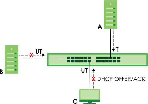
DHCP Snooping Status
Use this screen to look at various statistics about the DHCP snooping database.
The following table describes the labels in this screen.
label | description |
|---|---|
Database Status This section displays the current settings for the DHCP snooping database. You can configure them in the SECURITY > DHCP Snooping > DHCP Snp. Setup screen. | |
Agent URL | This field displays the location of the DHCP snooping database. |
Write Delay Timer | This field displays how long (in seconds) the Switch tries to complete a specific update in the DHCP snooping database before it gives up. |
Abort Timer | This field displays how long (in seconds) the Switch waits to update the DHCP snooping database after the current bindings change. |
Agent Running | This field displays the status of the current update or access of the DHCP snooping database. None: The Switch is not accessing the DHCP snooping database. Read: The Switch is loading dynamic bindings from the DHCP snooping database. Write: The Switch is updating the DHCP snooping database. |
Delay Timer Expiry | This field displays how much longer (in seconds) the Switch tries to complete the current update before it gives up. It displays Not Running if the Switch is not updating the DHCP snooping database right now. |
Abort Timer Expiry | This field displays when (in seconds) the Switch is going to update the DHCP snooping database again. It displays Not Running if the current bindings have not changed since the last update. |
Last Succeeded Time | This field displays the last time the Switch updated the DHCP snooping database successfully. |
Last Failed Time | This field displays the last time the Switch updated the DHCP snooping database unsuccessfully. |
Last Failed Reason | This field displays the reason the Switch updated the DHCP snooping database unsuccessfully. |
Counters This section displays historical information about the number of times the Switch successfully or unsuccessfully read or updated the DHCP snooping database. | |
Total Attempts | This field displays the number of times the Switch has tried to access the DHCP snooping database for any reason. |
Startup Failures | This field displays the number of times the Switch could not create or read the DHCP snooping database when the Switch started up or a new URL is configured for the DHCP snooping database. |
Successful Transfers | This field displays the number of times the Switch read bindings from or updated the bindings in the DHCP snooping database successfully. |
Failed Transfers | This field displays the number of times the Switch was unable to read bindings from or update the bindings in the DHCP snooping database. |
Successful Reads | This field displays the number of times the Switch read bindings from the DHCP snooping database successfully. |
Failed Reads | This field displays the number of times the Switch was unable to read bindings from the DHCP snooping database. |
Successful Writes | This field displays the number of times the Switch updated the bindings in the DHCP snooping database successfully. |
Failed Writes | This field displays the number of times the Switch was unable to update the bindings in the DHCP snooping database. |
Database Detail | |
First Successful Access | This field displays the first time the Switch accessed the DHCP snooping database for any reason. |
Last Ignored Bindings Counters This section displays the number of times and the reasons the Switch ignored bindings the last time it read bindings from the DHCP binding database. You can clear these counters by restarting the Switch or using CLI commands. | |
Binding Collisions | This field displays the number of bindings the Switch ignored because the Switch already had a binding with the same MAC address and VLAN ID. |
Invalid Interfaces | This field displays the number of bindings the Switch ignored because the port number was a trusted interface or does not exist anymore. |
Parse Failures | This field displays the number of bindings the Switch ignored because the Switch was unable to understand the binding in the DHCP binding database. |
Expired Leases | This field displays the number of bindings the Switch ignored because the lease time had already expired. |
Unsupported VLANs | This field displays the number of bindings the Switch ignored because the VLAN ID does not exist anymore. |
Last Ignored Time | This field displays the last time the Switch ignored any bindings for any reason from the DHCP binding database. |
Total Ignored Bindings Counters This section displays the reasons the Switch has ignored bindings any time it read bindings from the DHCP binding database. You can clear these counters by restarting the Switch or using CLI commands. | |
Binding Collisions | This field displays the number of bindings the Switch has ignored because the Switch already had a binding with the same MAC address and VLAN ID. |
Invalid Interfaces | This field displays the number of bindings the Switch has ignored because the port number was a trusted interface or does not exist anymore. |
Parse Failures | This field displays the number of bindings the Switch has ignored because the Switch was unable to understand the binding in the DHCP binding database. |
Expired Leases | This field displays the number of bindings the Switch has ignored because the lease time had already expired. |
Unsupported VLANs | This field displays the number of bindings the Switch has ignored because the VLAN ID does not exist anymore. |
DHCP Snooping Setup
Use this screen to enable DHCP snooping on the Switch (not on specific VLAN), specify the VLAN where the default DHCP server is located, and configure the DHCP snooping database. The DHCP snooping database stores the current bindings on a secure, external TFTP server so that they are still available after a restart.
The following table describes the labels in this screen.
label | description |
|---|---|
DHCP Snooping Setup | |
Active | Enable the switch button to enable DHCP snooping on the Switch. You still have to enable DHCP snooping on specific VLAN and specify trusted ports. |
DHCP VLAN | Select a VLAN ID if you want the Switch to forward DHCP packets to DHCP servers on a specific VLAN. You can enable Option 82 Profile in the SECURITY > DHCP Snooping > DHCP Snp. VLAN Setup screento help the DHCP servers distinguish between DHCP requests from different VLAN. Select Disable if you do not want the Switch to forward DHCP packets to a specific VLAN. |
Database If Timeout Interval is greater than Write Delay Interval, it is possible that the next update is scheduled to occur before the current update has finished successfully or timed out. In this case, the Switch waits to start the next update until it completes the current one. | |
Agent URL | Enter the location of the DHCP snooping database. The location should be expressed like this: tftp://{domain name or IP address}/directory, if applicable/file name; for example, tftp://192.168.10.1/database.txt. You can enter up to 256 printable ASCII characters except [ ? ], [ | ], [ ' ], [ " ], or [ , ]. |
Timeout Interval | Enter how long (10 – 65535 seconds) the Switch tries to complete a specific update in the DHCP snooping database before it gives up. |
Write Delay Interval | Enter how long (10 – 65535 seconds) the Switch waits to update the DHCP snooping database the first time the current bindings change after an update. Once the next update is scheduled, additional changes in current bindings are automatically included in the next update. |
Renew DHCP Snooping URL | Enter the location of a DHCP snooping database, and click Renew if you want the Switch to load it. You can use this to load dynamic bindings from a different DHCP snooping database than the one specified in Agent URL. When the Switch loads dynamic bindings from a DHCP snooping database, it does not discard the current dynamic bindings first. If there is a conflict, the Switch keeps the dynamic binding in volatile memory and updates the Binding Collisions counter in the DHCP Snooping Status screen. |
Apply | Click Apply to save your changes to the Switch’s run-time memory. The Switch loses these changes if it is turned off or loses power, so use the Save link on the top navigation panel to save your changes to the non-volatile memory when you are done configuring. |
Cancel | Click this to reset the values in this screen to their last-saved values. |
DHCP Snooping Port Setup
Use this screen to specify whether ports are trusted or untrusted ports for DHCP snooping.
You can also specify the maximum number for DHCP packets that each port (trusted or untrusted) can receive each second.
The following table describes the labels in this screen.
label | description |
|---|---|
Port | This field displays the port number. |
* | Settings in this row apply to all ports. Use this row only if you want to make some settings the same for all ports. Use this row first to set the common settings and then make adjustments on a port-by-port basis. |
Server Trusted state | Select whether this port is a trusted port (Trusted) or an untrusted port (Untrusted). Trusted ports are connected to DHCP servers or other switches, and the Switch discards DHCP packets from trusted ports only if the rate at which DHCP packets arrive is too high. Untrusted ports are connected to subscribers, and the Switch discards DHCP packets from untrusted ports in the following situations: • The packet is a DHCP server packet (for example, OFFER, ACK, or NACK). • The source MAC address and source IP address in the packet do not match any of the current bindings. • The packet is a RELEASE or DECLINE packet, and the source MAC address and source port do not match any of the current bindings. • The rate at which DHCP packets arrive is too high. |
Rate (pps) | Specify the maximum number for DHCP packets (1 – 256) that the Switch receives from each port each second. The Switch discards any additional DHCP packets. Enter 0 to disable this limit, which is recommended for trusted ports. |
Apply | Click Apply to save your changes to the Switch’s run-time memory. The Switch loses these changes if it is turned off or loses power, so use the Save link on the top navigation panel to save your changes to the non-volatile memory when you are done configuring. |
Cancel | Click this to reset the values in this screen to their last-saved values. |
DHCP Snooping VLAN Setup
Use this screen to enable DHCP snooping on each VLAN and to specify whether or not the Switch adds DHCP relay agent option 82 information to DHCP requests that the Switch relays to a DHCP server for each VLAN.
The following table describes the labels in this screen.
label | description |
|---|---|
Search VLAN by VID | Enter the VLAN ID you want to manage. Use a comma (,) to separate individual VLANs or a hyphen (-) to indicates a range of VLANs. For example, “3,4” or “3-9”. |
Search | Click this to display the specified range of VLANs in the section below. |
The Number of VLANs | This displays the number of VLAN search results. |
VID | This field displays the VLAN ID of each VLAN in the range specified above. If you configure the * VLAN, the settings are applied to all VLANs. |
Enabled | Select Yes to enable DHCP snooping on the VLAN. You still have to enable DHCP snooping on the Switch and specify trusted ports. |
Option 82 Profile | Select a pre-defined DHCP option 82 profile that the Switch applies to all ports in the specified VLANs. The Switch adds the information (such as slot number, port number, VLAN ID and/or system name) specified in the profile to DHCP requests that it broadcasts to the DHCP VLAN, if specified, or VLAN. You can specify the DHCP VLAN in the SECURITY > DHCP Snooping > DHCP Snp. Setup screen. |
Apply | Click Apply to save your changes to the Switch’s run-time memory. The Switch loses these changes if it is turned off or loses power, so use the Save link on the top navigation panel to save your changes to the non-volatile memory when you are done configuring. |
Cancel | Click this to reset the values in this screen to their last-saved values. |
DHCP Snooping VLAN Port Setup
Use this screen to apply a different DHCP option 82 profile to certain ports in a VLAN.
The following table describes the labels in this screen.
label | description |
|---|---|
Index | This field displays a sequential number for each entry. |
VID | This field displays the VLAN to which the ports belongs. |
Port | This field displays the ports to which the Switch applies the settings. |
Profile Name | This field displays the DHCP option 82 profile that the Switch applies to the ports. |
Add/Edit | Click Add/Edit to add a new entry or edit a selected one. |
Delete | Click Delete to remove the selected entries. |
Add/EDIT DHCP Snooping VLAN Ports
Use this screen to apply a different DHCP option 82 profile to certain ports in a VLAN.
Click Add/Edit, or select an entry and click Add/Edit in the SECURITY > IPv4 Source Guard > DHCP Snooping > DHCP Snp. VLAN Port Setup screen to display this screen.
The following table describes the labels in this screen.
label | description |
|---|---|
VID | Enter the ID number of the VLAN you want to configure here. |
Port | Enter the number of ports to which you want to apply the specified DHCP option 82 profile. You can enter multiple ports separated by (no space) comma (,) or hyphen (-) for a range. For example, enter “3-5” for ports 3, 4, and 5. Enter “3,5,7” for ports 3, 5, and 7. |
Option 82 Profile | Select a pre-defined DHCP option 82 profile that the Switch applies to the specified ports in this VLAN. The Switch adds the information (such as slot number, port number, VLAN ID and/or system name) specified in the profile to DHCP requests that it broadcasts to the DHCP VLAN, if specified, or VLAN. You can specify the DHCP VLAN in the SECURITY > DHCP Snooping > DHCP Snp. Setup screen. |
Apply | Click Apply to save your changes to the Switch’s run-time memory. The Switch loses these changes if it is turned off or loses power, so use the Save link on the top navigation panel to save your changes to the non-volatile memory when you are done configuring. |
Clear | Click Clear to clear the fields to the factory defaults. |
Cancel | Click Cancel to not save the configuration you make and return to the last screen. |
Port Security Overview
Port security allows only packets with dynamically learned MAC addresses and/or configured static MAC addresses to pass through a port on the Switch.
For maximum port security, enable this feature, disable MAC address learning and configure static MAC addresses for a port.
Port Security
The following table describes the labels in this screen.
label | description |
|---|---|
MAC Freeze | |
Port List | Enter the number of the ports (separated by a comma) on which you want to enable port security and disable MAC address learning. After you click MAC Freeze, all previously learned MAC addresses on the specified ports will become static MAC addresses and display in the SWITCHING > Static MAC Forwarding > Static MAC Forwarding screen. |
MAC Freeze | Click MAC Freeze to have the Switch automatically select the Active checkboxes and clear the Address Learning checkboxes only for the ports specified in the Port List. |
Port Security | |
Active | Enable the switch button to enable port security on the Switch. |
Port | This field displays the port number. |
* | Settings in this row apply to all ports. Use this row only if you want to make some of the settings the same for all ports. Use this row first to set the common settings and then make adjustments on a port-by-port basis. |
Active | Select this checkbox to enable the port security feature on this port. The Switch forwards packets whose MAC addresses is in the MAC address table on this port. Packets with no matching MAC addresses are dropped. Clear this checkbox to disable the port security feature. The Switch forwards all packets on this port. |
Address Learning | MAC address learning reduces outgoing broadcast traffic. For MAC address learning to occur on a port, the port itself must be active with address learning enabled. |
Limited Number of Learned MAC Address | Use this field to limit the number of (dynamic) MAC addresses that may be learned on a port. For example, if you set this field to "5" on port 2, then only the devices with these five learned MAC addresses may access port 2 at any one time. A sixth device must wait until one of the five learned MAC addresses ages out. MAC address aging out time can be set in the SYSTEM > Switch Setup screen. The valid range is from “0” to “32K”. “0” means this feature is disabled. |
Apply | Click Apply to save your changes to the Switch’s run-time memory. The Switch loses these changes if it is turned off or loses power, so use the Save link on the top navigation panel to save your changes to the non-volatile memory when you are done configuring. |
Cancel | Click Cancel to begin configuring this screen afresh. |