SWITCHING
Loop Guard Overview
Loop guard (LG) allows you to configure the Switch to shut down a port if it detects that packets sent out on that port loop back to the Switch. While you can use Spanning Tree Protocol (STP) to prevent loops in the core of your network. STP cannot prevent loops that occur on the edge of your network.
Loop Guard vs. STP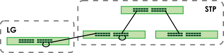
Loop guard is designed to handle loop problems on the edge of your network. This can occur when a port is connected to a Switch that is in a loop state. Loop state occurs as a result of human error. It happens when two ports on a switch are connected with the same cable. When a switch in loop state sends out broadcast messages the messages loop back to the switch and are re-broadcast again and again causing a broadcast storm.
If a switch (not in loop state) connects to a switch in loop state, then it will be affected by the switch in loop state in the following way:
• will receive broadcast messages sent out from the switch in loop state.
• will receive its own broadcast messages that it sends out as they loop back. It will then re-broadcast those messages again.
Loop Guard Setup
The following table describes the labels in this screen.
label | description |
|---|---|
Active | Enable the switch button to activate loop guard function on the Switch. The Switch generates syslog, internal log messages as well as SNMP traps when it shuts down a port through the loop guard feature. |
Port | This field displays the port number. |
* | Settings in this row apply to all ports. Use this row only if you want to make some settings the same for all ports. Use this row first to set the common settings and then make adjustments on a port-by-port basis. |
Active | Select this checkbox to enable the loop guard feature on this port. The Switch sends broadcast and multicast probe packets from this port to check if the switch it is connected to is in loop state. If the switch that this port is connected is in loop state the Switch will shut down this port. Clear this checkbox to disable the loop guard feature. |
Apply | Click Apply to save your changes to the Switch’s run-time memory. The Switch loses these changes if it is turned off or loses power, so use the Save link on the top navigation panel to save your changes to the non-volatile memory when you are done configuring. |
Cancel | Click Cancel to begin configuring this screen afresh. |
Mirroring Overview
Port mirroring allows you to copy a traffic flow to a monitor port (the port you copy the traffic to) in order that you can examine the traffic from the monitor port without interference.
Port Mirroring Setup
Use this screen to select a monitor port and specify the traffic flow to be copied to the monitor port.
The following table describes the labels in this screen.
LABEL | DESCRIPTION |
|---|---|
Active | Enable the switch button to activate port mirroring on the Switch. Disable the switch to disable the feature. |
Monitor Port | The monitor port is the port you copy the traffic to in order to examine it in more detail without interfering with the traffic flow on the original ports. Enter the port number of the monitor port. |
Port | This field displays the port number. |
* | Settings in this row apply to all ports. Use this row only if you want to make some settings the same for all ports. Use this row first to set the common settings and then make adjustments on a port-by-port basis. |
Mirrored | Select this option to mirror the traffic on a port. |
Direction | Specify the direction of the traffic to mirror by selecting from the drop-down list box. Choices are Egress (outgoing), Ingress (incoming) and Both. |
Apply | Click Apply to save your changes to the Switch’s run-time memory. The Switch loses these changes if it is turned off or loses power, so use the Save link on the top navigation panel to save your changes to the non-volatile memory when you are done configuring. |
Cancel | Click Cancel to reset the fields. |
Multicast Overview
Traditionally, IP packets are transmitted in one of either two ways – Unicast (one sender to one recipient) or Broadcast (one sender to everybody on the network). Multicast delivers IP packets to just a group of hosts on the network.
IGMP (Internet Group Management Protocol) is a network-layer protocol used to establish membership in a multicast group – it is not used to carry user data. Refer to RFC 1112, RFC 2236 and RFC 3376 for information on IGMP versions 1, 2 and 3 respectively.
IP Multicast Addresses
In IPv4, a multicast address allows a device to send packets to a specific group of hosts (multicast group) in a different subnetwork. A multicast IP address represents a traffic receiving group, not individual receiving devices. IP addresses in the Class D range (224.0.0.0 to 239.255.255.255) are used for IP multicasting. Certain IP multicast numbers are reserved by IANA for special purposes (see the IANA website for more information).
IGMP Snooping
A Switch can passively snoop on IGMP packets transferred between IP multicast routers or switches and IP multicast hosts to learn the IP multicast group membership. It checks IGMP packets passing through it, picks out the group registration information, and configures multicasting accordingly. IGMP snooping allows the Switch to learn multicast groups without you having to manually configure them.
The Switch forwards multicast traffic destined for multicast groups (that it has learned from IGMP snooping or that you have manually configured) to ports that are members of that group. IGMP snooping generates no additional network traffic, allowing you to significantly reduce multicast traffic passing through your Switch.
IGMP Snooping and VLANs
The Switch can perform IGMP snooping on up to 16 VLANs. You can configure the Switch to automatically learn multicast group membership of any VLANs. The Switch then performs IGMP snooping on the first 16 VLANs that send IGMP packets. This is referred to as auto mode. Alternatively, you can specify the VLANs that IGMP snooping should be performed on. This is referred to as fixed mode. In fixed mode the Switch does not learn multicast group membership of any VLANs other than those explicitly added as an IGMP snooping VLAN.
IPv4 Multicast Status
This screen shows the IPv4 multicast group information.
The following table describes the labels in this screen.
label | description |
|---|---|
Index | This is the index number of the entry. |
VID | This field displays the multicast VLAN ID. |
Port | This field displays the port number that belongs to the multicast group. |
Multicast Group | This field displays IP multicast group addresses. |
IGMP Snooping
The following table describes the labels in this screen.
label | description |
|---|---|
Active | Enable the switch button to enable IGMP Snooping to forward group multicast traffic only to ports that are members of that group. |
Querier | Select this to allow the Switch to send IGMP General Query messages to the VLANs with the multicast hosts attached. |
Report Proxy | Select this to allow the Switch to act as the IGMP report proxy and leave proxy. It will report group changes to a connected multicast router. The Switch not only checks IGMP packets between multicast routers or switches and multicast hosts to learn the multicast group membership, but also replaces the source MAC address in an IGMP v1/v2 report with its own MAC address before forwarding to the multicast router or switch. When the Switch receives more than one IGMP v1/v2 join report that requests to join the same multicast group, it only sends a new join report with its MAC address. This helps reduce the number of multicast join reports passed to the multicast router or switch. The Switch sends a leave message with its MAC address to the multicast router or switch only when it receives the leave message from the last host in a multicast group. |
Host Timeout | Specify the time (from 1 to 16711450) in seconds that elapses before the Switch removes an IGMP group membership entry if it does not receive report messages from the port. |
802.1p Priority | Select a priority level (0 – 7) to which the Switch changes the priority in outgoing IGMP control packets. Otherwise, select No-Change to not replace the priority. |
Unknown Multicast Frame | Specify the action to perform when the Switch receives an unknown multicast frame. Select Drop to discard the frames. Select Flooding to send the frames to all ports. |
Reserved Multicast Group | The IP address range of 224.0.0.0 to 224.0.0.255 are reserved for multicasting on the local network only. For example, 224.0.0.1 is for all hosts on a local network segment and 224.0.0.9 is used to send RIP routing information to all RIP v2 routers on the same network segment. A multicast router will not forward a packet with the destination IP address within this range to other networks. See the IANA web site for more information. The layer-2 multicast MAC addresses used by Cisco layer-2 protocols, 01:00:0C:CC:CC:CC and 01:00:0C:CC:CC:CD, are also included in this group. Specify the action to perform when the Switch receives a frame with a reserved multicast address. • Select Flooding to send the frames to all ports. • Select Drop to discard the frames. |
Use this section to configure IGMP Snooping on each port. | |
Port | This field displays the port number. |
* | Settings in this row apply to all ports. Use this row only if you want to make some settings the same for all ports. Use this row first to set the common settings and then make adjustments on a port-by-port basis. Changes in this row are copied to all the ports as soon as you make them. |
Normal Leave | In normal leave mode, when the Switch receives an IGMP leave message from a host on a port, it forwards the message to the multicast router. The multicast router then sends out an IGMP Group-Specific Query (GSQ) message to determine whether other hosts connected to the port should remain in the specific multicast group. The Switch forwards the query message to all hosts connected to the port and waits for IGMP reports from hosts to update the forwarding table. This defines how many seconds the Switch waits for an IGMP report before removing an IGMP snooping membership entry when an IGMP leave message is received on this port from a host. |
Fast Leave | In fast leave mode, right after receiving an IGMP leave message from a host on a port, the Switch itself sends out an IGMP Group-Specific Query (GSQ) message to determine whether other hosts connected to the port should remain in the specific multicast group. This helps speed up the leave process. This defines how many seconds the Switch waits for an IGMP report before removing an IGMP snooping membership entry when an IGMP leave message is received on this port from a host. |
IGMP Querier Mode | The Switch treats an IGMP query port as being connected to an IGMP multicast router (or server). The Switch forwards IGMP join or leave packets to an IGMP query port. Select Auto to have the Switch use the port as an IGMP query port if the port receives IGMP query packets. Select Fixed to have the Switch always use the port as an IGMP query port. Select this when you connect an IGMP multicast server to the port. Select Edge to stop the Switch from using the port as an IGMP query port. The Switch will not keep any record of an IGMP router being connected to this port. The Switch does not forward IGMP join or leave packets to this port. |
Apply | Click Apply to save your changes to the Switch’s run-time memory. The Switch loses these changes if it is turned off or loses power, so use the Save link on the top navigation panel to save your changes to the non-volatile memory when you are done configuring. |
Cancel | Click Cancel to begin configuring this screen afresh. |
IGMP Snooping VLAN
The following table describes the labels in this screen.
label | description |
|---|---|
IGMP Snooping VLAN | |
Mode | Select auto to have the Switch learn multicast group membership information of any VLANs automatically. Select fixed to have the Switch only learn multicast group membership information of the VLANs that you specify below. In either auto or fixed mode, the Switch can learn up to 16 VLANs. The Switch drops any IGMP control messages which do not belong to these 16 VLANs. You must also enable IGMP snooping in the SWITCHING > Multicast > IPv4 Multicast > IGMP Snooping screen first. |
Apply | Click Apply to save your changes to the Switch’s run-time memory. The Switch loses these changes if it is turned off or loses power, so use the Save link on the top navigation panel to save your changes to the non-volatile memory when you are done configuring. |
Cancel | Click Cancel to begin configuring this screen afresh. |
VLAN Use this section of the screen to add VLANs on which the Switch is to perform IGMP snooping. | |
Index | This is the index number of the IGMP snooping VLAN entry in the table. |
Name | This field displays the descriptive name for this VLAN group. |
VID | This field displays the ID number of the VLAN group. |
Select an entry’s checkbox to select a specific entry. Otherwise, select the checkbox in the table heading row to select all entries. | |
Add/Edit | Click Add/Edit to create a new entry or edit a selected one. |
Delete | Click Delete to remove the selected entries. |
Add/Edit IGMP Snooping VLANs
This screen allows you to add an IGMP snooping VLAN or edit an existing one.
To access this screen, click the Add/Edit button or select an entry from the list and click the Add/Edit button.
The following table describes the labels in this screen.
label | description |
|---|---|
Name | Enter the descriptive name of the VLAN for identification purposes. You can enter up to 32 printable ASCII characters except [ ? ], [ | ], [ ' ], [ " ] or [ , ]. |
VID | Enter the ID of a static VLAN; the valid range is between 1 and 4094. |
Apply | Click Apply to save your changes to the Switch’s run-time memory. The Switch loses these changes if it is turned off or loses power, so use the Save link on the top navigation panel to save your changes to the non-volatile memory when you are done configuring. |
Clear | Click Clear to clear the fields to the factory defaults. |
Cancel | Click Cancel to not save the configuration you make and return to the last screen. |
Static Multicast Forwarding Overview
A multicast MAC address or multicast IP address is the MAC address or IP address of a multicast group, and not a receiving device.
A static multicast address is a multicast MAC address or multicast IPv4 address that has been manually entered in the multicast table. This identifies the destination of the multicast content. Multicast IPv4 addresses uses the Class D IP addresses range 224.0.0.0 to 239.255.255.255. Multicast MAC addresses have a “1” as the last binary bit of the first octet pair (for example, 01:00:5e:00:00:0A). Static multicast addresses do not age out.
If a multicast group has no members, then the Switch cannot forward to specific ports unless you configure static (manual) multicast entries. The Switch will either flood the multicast frames to all ports (default) or drop them. With static multicast forwarding, you can forward these multicasts to ports within a VLAN group.
No Multicast Forwarding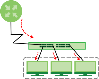
Static Multicast Forwarding By MAC
Use this screen to view and configure static multicast MAC addresses for ports to receive the multicast stream.The following table describes the labels in this screen.
label | description |
|---|---|
Index | This is the index number of the static multicast MAC address rule. |
Active | This field displays whether a static multicast MAC address forwarding rule is active or not. You may temporarily deactivate a rule without deleting it. |
Name | This field displays the descriptive name for identification purposes for a static multicast MAC address-forwarding rule. |
MAC Address | This field displays the multicast MAC address that identifies a multicast group. |
VID | This field displays the ID number of a VLAN group to which frames containing the specified multicast MAC address will be forwarded. |
Port | This field displays the ports within an identified VLAN group to which frames containing the specified multicast MAC address will be forwarded. |
Select an entry’s checkbox to select a specific entry. Otherwise, select the checkbox in the table heading row to select all entries. | |
Add/Edit | Click Add/Edit to add a new rule or edit a selected one. |
Delete | Click Delete to remove the selected rules. |
Add/Edit Static Multicast Forwarding By MAC
Use this screen to add a static multicast MAC address rule for ports to receive the multicast stream.
Click Add/Edit, or select an entry and click Add/Edit in the SWITCHING > Multicast > Static Multicast Forwarding By MAC to display this screen.
The following table describes the labels in this screen
label | description |
|---|---|
Active | Enable the switch button to activate your rule. You may temporarily deactivate a rule without deleting it by disabling the switch. |
Name | Enter a descriptive name (up to 32 printable ASCII characters except [ ? ], [ | ], [ ' ], [ " ], or [ , ]) for this static multicast MAC address forwarding rule. This is for identification only. |
MAC Address | Enter a multicast MAC address which identifies the multicast group. The last binary bit of the first octet pair in a multicast MAC address must be 1. For example, the first octet pair 00000001 is 01 in hexadecimal, so 01:00:5e:00:00:0A and 01:00:5e:00:00:27 are valid multicast MAC addresses. |
VID | You can forward frames with matching destination multicast MAC address to ports within a VLAN group. Enter the ID that identifies the VLAN group here. If you do NOT have a specific target VLAN, enter 1. |
Port | Enter the ports where frames with destination multicast MAC address that matched the entry above are forwarded. You can enter multiple ports separated by (no space) comma (,) or hyphen (-). For example, enter “3-5” for ports 3, 4, and 5. Enter “3,5,7” for ports 3, 5, and 7. |
Apply | Click Apply to save your changes to the Switch’s run-time memory. The Switch loses these changes if it is turned off or loses power, so use the Save link on the top navigation panel to save your changes to the non-volatile memory when you are done configuring. |
Clear | Click Clear to clear the fields to the factory defaults. |
Cancel | Click Cancel to not save the configuration you make and return to the last screen. |
ONVIF Overview
IP-based security products use a specific protocol for communication. One of the most common protocols is ONVIF (Open Network Video Interface Forum). ONVIF is a standard interface for interoperability of IP-based security products.
When ONVIF is enabled and configured, the Switch can obtain information from connected ONVIF-compatible devices, such as a device’s system name and IP address. This lets you know which ONVIF-compatible devices, for example IP cameras and NVR (network video recorders), are connected to the Switch.
ONVIF
This screen lets you turn on the ONVIF protocol on the Switch and its Ethernet ports.
The following table describes the labels in this screen.
label | description |
|---|---|
Active | Select Active to allow this Switch to send ONVIF packets to discover or scan for ONVIF-compatible IP-based security devices connected to its ports. Make sure to enter the port numbers in Port to allow discovery of ONVIF-compatible devices. |
Apply | Click Apply to save your changes to the Switch’s run-time memory. The Switch loses these changes if it is turned off or loses power, so use the Save link on the top navigation panel to save your changes to the non-volatile memory when you are done configuring. |
Cancel | Click this to reset the values in this screen to their last-saved values. |
VLAN | |
Select an entry’s checkbox to select a specific entry. Otherwise, select the checkbox in the table heading row to select all entries. | |
Index | This is the index number of the ONVIF entry in the table. |
VID | This field displays the VLAN to which the ports belong. |
Port | This field displays the ports to which the Switch applies the settings. |
Add/Edit | Click Add/Edit to add a new entry or edit a selected one. |
Delete | Check the entries that you want to remove, then click the Delete button. |
Add/Edit ONVIF Protocol
The following table describes the labels in this screen.
label | description |
|---|---|
VID | Enter the ID number of the VLAN to run ONVIF. |
Port | Enter the port numbers to allow discovery of ONVIF-compatible devices. You can enter multiple ports separated by comma (,) or hyphen (–) without spaces. For example, enter “3–5” for ports 3, 4, and 5. Enter “3,5,7” for ports 3, 5, and 7. |
Apply | Click Apply to save your changes to the Switch’s run-time memory. The Switch loses these changes if it is turned off or loses power, so use the Save link on the top navigation panel to save your changes to the non-volatile memory when you are done configuring. |
Clear | Click Clear to reset the fields to the factory defaults. |
Cancel | Click Cancel to reset the fields to your previous configuration. |
DiffServ Overview
Quality of Service (QoS) is used to prioritize source-to-destination traffic flows. All packets in the flow are given the same priority. You can use CoS (class of service) to give different priorities to different packet types.
DiffServ is a class of service (CoS) model that marks packets so that they receive specific per-hop treatment at DiffServ-compliant network devices along the route based on the application types and traffic flow. Packets are marked with DiffServ Code Points (DSCPs) indicating the level of service desired. This allows the intermediary DiffServ-compliant network devices to handle the packets differently depending on the code points without the need to negotiate paths or remember state information for every flow. In addition, applications do not have to request a particular service or give advanced notice of where the traffic is going.
DiffServ
Activate DiffServ to apply marking rules or IEEE 802.1p priority mapping on the selected ports.
The following table describes the labels in this screen.
label | description |
|---|---|
Active | Enable the switch button to enable Diffserv on the Switch. |
Port | This field displays the index number of a port on the Switch. |
* | Settings in this row apply to all ports. Use this row only if you want to make some settings the same for all ports. Use this row first to set the common settings and then make adjustments on a port-by-port basis. Changes in this row are copied to all the ports as soon as you make them. |
Active | Select Active to enable Diffserv on the port. |
Apply | Click Apply to save your changes to the Switch’s run-time memory. The Switch loses these changes if it is turned off or loses power, so use the Save link on the top navigation panel to save your changes to the non-volatile memory when you are done configuring. |
Cancel | Click Cancel to begin configuring this screen afresh. |
DSCP-to-IEEE 802.1p Priority Settings
You can configure the DSCP to IEEE 802.1p mapping to allow the Switch to prioritize all traffic based on the incoming DSCP value according to the DiffServ to IEEE 802.1p mapping table.
The following table shows the default DSCP-to-IEEE802.1p mapping.
DSCP VALUE | 0 – 7 | 8 – 15 | 16 – 23 | 24 – 31 | 32 – 39 | 40 – 47 | 48 – 55 | 56 – 63 |
IEEE 802.1p | 0 | 1 | 2 | 3 | 4 | 5 | 6 | 7 |
Configure DSCP Settings
The following table describes the labels in this screen.
label | description |
|---|---|
0 … 63 | This is the DSCP classification identification number. To set the IEEE 802.1p priority mapping, select the priority level from the drop-down list box. |
Apply | Click Apply to save your changes to the Switch’s run-time memory. The Switch loses these changes if it is turned off or loses power, so use the Save link on the top navigation panel to save your changes to the non-volatile memory when you are done configuring. |
Cancel | Click Cancel to begin configuring this screen afresh. |
Queuing Method Overview
Queuing is used to help solve performance degradation when there is network congestion. Use the Queuing Method screen to configure queuing algorithms for outgoing traffic. See also Priority Queue Assignment in the SWITCHING > QoS > Priority Queue screen and 802.1p Priority in the PORT > Port Setup > Port Setup screen for related information.
Queuing algorithms allow switches to maintain separate queues for packets from each individual source or flow and prevent a source from monopolizing the bandwidth.
Strictly Priority Queuing
Strictly Priority Queuing (SPQ) services queues based on priority only. As traffic comes into the Switch, traffic on the highest priority queue, Q7 is transmitted first. When that queue empties, traffic on the next highest-priority queue, Q6 is transmitted until Q6 empties, and then traffic is transmitted on Q5 and so on. If higher priority queues never empty, then traffic on lower priority queues never gets sent. SPQ does not automatically adapt to changing network requirements.
Weighted Fair Queuing
Weighted Fair Queuing is used to guarantee each queue's minimum bandwidth based on its bandwidth weight (portion) (the number you configure in the Weight field) when there is traffic congestion. WFQ is activated only when a port has more traffic than it can handle. Queues with larger weights get more guaranteed bandwidth than queues with smaller weights. This queuing mechanism is highly efficient in that it divides any available bandwidth across the different traffic queues. By default, the weight for Q0 is 1, for Q1 is 2, for Q2 is 3, and so on.
Weighted Round Robin Scheduling (WRR)
Round Robin Scheduling services queues on a rotating basis and is activated only when a port has more traffic than it can handle. A queue is given an amount of bandwidth irrespective of the incoming traffic on that port. This queue then moves to the back of the list. The next queue is given an equal amount of bandwidth, and then moves to the end of the list; and so on, depending on the number of queues being used. This works in a looping fashion until a queue is empty.
Weighted Round Robin Scheduling (WRR) uses the same algorithm as round robin scheduling, but services queues based on their priority and queue weight (the number you configure in the queue Weight field) rather than a fixed amount of bandwidth. WRR is activated only when a port has more traffic than it can handle. Queues with larger weights get more service than queues with smaller weights. This queuing mechanism is highly efficient in that it divides any available bandwidth across the different traffic queues and returns to queues that have not yet emptied.
Configure Queuing
Use this screen to set priorities for the queues of the Switch. This distributes bandwidth across the different traffic queues.
The following table describes the labels in this screen.
label | Description |
|---|---|
Port | This label shows the port you are configuring. |
* | Settings in this row apply to all ports. Use this row only if you want to make some settings the same for all ports. Use this row first to set the common settings and then make adjustments on a port-by-port basis. |
Method | Select SPQ (Strictly Priority Queuing), WFQ (Weighted Fair Queuing) or WRR (Weighted Round Robin). Strictly Priority Queuing services queues based on priority only. When the highest priority queue empties, traffic on the next highest-priority queue begins. Q7 has the highest priority and Q0 the lowest. Weighted Fair Queuing is used to guarantee each queue's minimum bandwidth based on their bandwidth portion (weight) (the number you configure in the Weight field). Queues with larger weights get more guaranteed bandwidth than queues with smaller weights. Weighted Round Robin Scheduling services queues on a rotating basis based on their queue weight (the number you configure in the queue Weight field). Queues with larger weights get more service than queues with smaller weights. |
Weight | When you select WFQ or WRR, enter the queue weight here. Bandwidth is divided across the different traffic queues according to their weights. |
Hybrid-SPQ Lowest-Queue | This field is applicable only when you select WFQ or WRR. Select a queue (Q0 to Q7) to have the Switch use SPQ to service the subsequent queues after and including the specified queue for the port. For example, if you select Q5, the Switch services traffic on Q5, Q6 and Q7 using SPQ. Select None to always use WFQ or WRR for the port. |
Apply | Click Apply to save your changes to the Switch’s run-time memory. The Switch loses these changes if it is turned off or loses power, so use the Save link on the top navigation panel to save your changes to the non-volatile memory when you are done configuring. |
Cancel | Click Cancel to begin configuring this screen afresh. |
Priority Queue Overview
IEEE 802.1p defines up to eight separate traffic types by inserting a tag into a MAC-layer frame that contains bits to define class of service. Frames without an explicit priority tag are given the default priority of the ingress port. Use this screen to configure the priority level-to-physical queue mapping. The Switch has eight physical queues that you can map to the eight priority levels.
On the Switch, traffic assigned to higher index queues gets through faster while traffic in lower index queues is dropped if the network is congested.
Priority Queue
Use this screen to assign priority level to each queue.
The following table describes the related labels in this screen.
label | description |
|---|---|
Priority Queue Assignment The following descriptions are based on the traffic types defined in the IEEE 802.1d standard (which incorporates the 802.1p). To map a priority level to a physical queue, select a physical queue from the drop-down menu on the right. | |
Priority 7 | Typically used for network control traffic such as router configuration messages. |
Priority 6 | Typically used for voice traffic that is especially sensitive to jitter (jitter is the variations in delay). |
Priority 5 | Typically used for video that consumes high bandwidth and is sensitive to jitter. |
Priority 4 | Typically used for controlled load, latency-sensitive traffic such as SNA (Systems Network Architecture) transactions. |
Priority 3 | Typically used for “excellent effort” or better than best effort and would include important business traffic that can tolerate some delay. |
Priority 2 | This is for “spare bandwidth”. |
Priority 1 | This is typically used for non-critical “background” traffic such as bulk transfers that are allowed but that should not affect other applications and users. |
Priority 0 | Typically used for best-effort traffic. |
Apply | Click Apply to save your changes to the Switch’s run-time memory. The Switch loses these changes if it is turned off or loses power, so use the Save link on the top navigation panel to save your changes to the non-volatile memory when you are done configuring. |
Cancel | Click Cancel to reset the fields. |
Bandwidth Control Overview
Bandwidth control means defining a maximum allowable bandwidth for incoming and/or out-going traffic flows on a port.
Bandwidth Control
The following table describes the related labels in this screen.
label | description |
|---|---|
Active | Enable the switch button to enable bandwidth control on the Switch. |
Port | This field displays the port number. |
* | Settings in this row apply to all ports. Use this row only if you want to make some settings the same for all ports. Use this row first to set the common settings and then make adjustments on a port-by-port basis. |
Active | Select this checkbox to activate ingress rate limits on this port. |
Ingress Rate | Specify the maximum bandwidth allowed in kilobits per second (Kbps) for the incoming traffic flow on a port. |
Active | Select this checkbox to activate egress rate limits on this port. |
Egress Rate | Specify the maximum bandwidth allowed in kilobits per second (Kbps) for the out-going traffic flow on a port. |
Apply | Click Apply to save your changes to the Switch’s run-time memory. The Switch loses these changes if it is turned off or loses power, so use the Save link on the top navigation panel to save your changes to the non-volatile memory when you are done configuring. |
Cancel | Click Cancel to reset the fields. |