VLAN Overview
This chapter shows you how to configure 802.1Q tagged and port-based VLANs.
The type of screen you see here depends on the VLAN Type you selected in the SYSTEM > Switch Setup screen.
Introduction to IEEE 802.1Q Tagged VLANs
A tagged VLAN uses an explicit tag (VLAN ID) in the MAC header to identify the VLAN membership of a frame across bridges – they are not confined to the switch on which they were created. The VLANs can be created statically by hand. The VLAN ID associates a frame with a specific VLAN and provides the information that switches need to process the frame across the network. A tagged frame is 4 bytes longer than an untagged frame and contains 2 bytes (16 Bits) of TPID (Tag Protocol Identifier, residing within the type or length field of the Ethernet frame) and 2 bytes (16 Bits) of TCI (Tag Control Information, starts after the source address field of the Ethernet frame). The TCI field consists of three fields: User Priority, CFI (Canonical Format Indicator), and VLAN ID.
The CFI (Canonical Format Indicator) is a single-bit flag, always set to zero for Ethernet switches. If a frame received at an Ethernet port has a CFI set to 1, then that frame should not be forwarded as it is to an untagged port. The remaining twelve bits define the VLAN ID, giving a possible maximum number of 4096 VLANs. Note that user priority and VLAN ID are independent of each other. A frame with VID (VLAN Identifier) of null (0) is called a priority frame, meaning that only the priority level is significant and the default VID of the ingress port is given as the VID of the frame. Of the 4096 possible VIDs, a VID of 0 is used to identify priority frames and value 4095 (FFF) is reserved, so the maximum possible VLAN configurations are 4094.
TPID 16 Bits | User Priority 3 Bits | CFI 1 Bit | VLAN ID 12 Bits |
Each port on the Switch is capable of passing tagged or untagged frames. To forward a frame from an 802.1Q VLAN-aware switch to an 802.1Q VLAN-unaware switch, the Switch first decides where to forward the frame and then strips off the VLAN tag. To forward a frame from an 802.1Q VLAN-unaware switch to an 802.1Q VLAN-aware switch, the Switch first decides where to forward the frame, and then inserts a VLAN tag reflecting the ingress port's default VID. The default PVID is VLAN 1 for all ports, but this can be changed.
A broadcast frame (or a multicast frame for a multicast group that is known by the system) is duplicated only on ports that are members of the VID (except the ingress port itself), thus confining the broadcast to a specific domain.
Port VLAN Trunking
Enable VLAN Trunking on a port to allow frames belonging to unknown VLAN groups to pass through that port. This is useful if you want to set up VLAN groups on end devices without having to configure the same VLAN groups on intermediary devices.
SYSTEM > Switch Setup: Select VLAN Type (With Access L3 License)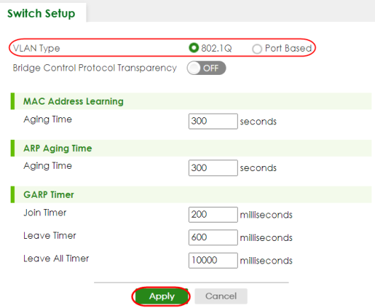
VLAN Status
Use this screen to view and search all VLAN groups.
The following table describes the labels in this screen.
label | description |
|---|---|
VLAN Search by VID | Enter (an) existing VLAN ID numbers (use a comma (,) to separate individual VLANs or a hyphen (-) to indicate a range of VLANs. For example, “3,4” or “3-9”) and click Search to display only the specified VLANs in the list below. Leave this field blank and click Search to display all VLANs configured on the Switch. |
The Number of VLAN | This is the number of VLANs configured on the Switch. |
The Number of Search Results | This is the number of VLANs that match the searching criteria and display in the list below. This field displays only when you use the Search button to look for certain VLANs. |
Index | This is the VLAN index number. Click an index number to view more VLAN details. |
VID | This is the VLAN identification number that was configured in the corresponding VLAN configuration screen. |
Name | This fields shows the descriptive name of the VLAN. |
Tagged Port | This field shows the tagged ports that are participating in the VLAN. |
Untagged Port | This field shows the untagged ports that are participating in the VLAN. |
Elapsed Time | This field shows how long it has been since a normal VLAN was registered or a static VLAN was set up. |
Status | This field shows how this VLAN was added to the Switch. Static: added as a permanent entry. |
VLAN Details
Use this screen to view detailed port settings and status of the VLAN group. Click an index number in the VLAN Status screen to display VLAN details.
The following table describes the labels in this screen.
label | description |
|---|---|
VID | This is the VLAN identification number that was configured in the corresponding VLAN configuration screen. |
Elapsed Time | This field shows how long it has been since a normal VLAN was registered or a static VLAN was set up. |
Status | This field shows how this VLAN was added to the Switch. Static: added as a permanent entry. |
Port Number | This section displays the ports that are participating in a VLAN. A tagged port is marked as T, an untagged port is marked as U and ports not participating in a VLAN are marked as “–“. |
Static VLAN
Use this screen to view and configure a static VLAN for the Switch.
The following table describes the related labels in this screen.
label | Description |
|---|---|
VID | This field displays the ID number of the VLAN group. |
Active | This field indicates whether the VLAN settings are enabled or disabled. |
Name | This field displays the descriptive name for this VLAN group. |
Select an entry’s checkbox to select a specific entry. Otherwise, select the checkbox in the table heading row to select all entries. | |
Add/Edit | Click Add/Edit to add a new static VLAN or edit a selected one. |
Delete | Click Delete to remove the selected static VLAN. |
Add/Edit a Static VLAN
Use this screen to configure a static VLAN for the Switch. Click Add/Edit, or select an entry and click Add/Edit in the SWITCHING > VLAN > VLAN Setup > Static VLAN screen to display this screen.
The following table describes the related labels in this screen.
label | Description |
|---|---|
Active | Enable the switch button to activate the VLAN settings. |
Name | Enter a descriptive name for the VLAN group for identification purposes. This name consists of up to 64 printable ASCII characters. The string should not contain [ ? ], [ | ], [ ' ], [ " ], or [ , ]. |
VLAN Group ID | Enter the VLAN ID for this static entry; the valid range is between 1 and 4094. |
Port | The port number identifies the port you are configuring. |
* | Settings in this row apply to all ports. Use this row only if you want to make some settings the same for all ports. Use this row first to set the common settings and then make adjustments on a port-by-port basis. |
Control | Select Normal for the port to dynamically join this VLAN group. This is the default selection. Select Fixed for the port to be a permanent member of this VLAN group. Select Forbidden if you want to prohibit the port from joining this VLAN group. |
Tagging | Select Tx Tagging if you want outgoing traffic to contain this VLAN tag. Otherwise, to ensure that VLAN-unaware devices (such as computers and hubs) can receive frames properly, clear the Tx Tagging checkbox to set the Switch to remove VLAN tags before sending. |
Apply | Click Apply to save your changes to the Switch’s run-time memory. The Switch loses these changes if it is turned off or loses power, so use the Save link on the top navigation panel to save your changes to the non-volatile memory when you are done configuring. |
Clear | Click Clear to clear the fields to the factory defaults. |
Cancel | Click Cancel to not save the configuration you make and return to the last screen. |
VLAN Port Setup
Use this screen to configure the static VLAN (IEEE 802.1Q) settings on a port.
The following table describes the labels in this screen.
label | description |
|---|---|
Port | This field displays the port number. |
* | Settings in this row apply to all ports. Use this row only if you want to make some settings the same for all ports. Use this row first to set the common settings and then make adjustments on a port-by-port basis. |
Ingress Check | If this checkbox is selected, the Switch discards incoming frames on a port for VLANs that do not include this port in its member set. Clear this checkbox to disable ingress filtering. |
PVID | A PVID (Port VLAN ID) is a tag that adds to incoming untagged frames received on a port so that the frames are forwarded to the VLAN group that the tag defines. Enter a number between 1and 4094 as the port VLAN ID. |
Acceptable Frame Type | Specify the type of frames allowed on a port. Choices are All, Tag Only and Untag Only. Select All from the drop-down list box to accept all untagged or tagged frames on this port. This is the default setting. Select Tag Only to accept only tagged frames on this port. All untagged frames will be dropped. Select Untag Only to accept only untagged frames on this port. All tagged frames will be dropped. |
VLAN Trunking | Enable VLAN Trunking on ports connected to other switches or routers (but not ports directly connected to end users) to allow frames belonging to unknown VLAN groups to pass through the Switch. |
Isolation | Select this to allows this port to communicate only with the CPU management port and the ports on which the isolation feature is NOT enabled. |
Apply | Click Apply to save your changes to the Switch’s run-time memory. The Switch loses these changes if it is turned off or loses power, so use the Save link on the top navigation panel to save your changes to the non-volatile memory when you are done configuring. |
Cancel | Click Cancel to begin configuring this screen afresh. |
Voice VLAN
Voice VLAN is a VLAN that is specifically allocated for voice traffic. It ensures that the sound quality of an IP phone is preserved from deteriorating when the data traffic on the Switch ports is high. It groups the voice traffic with defined priority into an assigned VLAN which enables the separation of voice and data traffic coming onto the Switch port.
The Switch can determine whether a received packet is
• an untagged voice packet when the incoming port is a fixed port for voice VLAN.
• a tagged voice packet when the incoming port and VLAN tag belongs to a voice VLAN.
It then checks the source packet’s MAC address against an OUI list. If a match is found, the packet is considered as a voice packet.
You can set priority level to the Voice VLAN and add MAC address of IP phones from specific manufacturers by using its ID from the Organizationally Unique Identifiers (OUI).
The following table describes the fields in the above screen.
label | description |
|---|---|
Voice VLAN Global Setup | |
Voice VLAN | Click the second radio button if you want to enable the Voice VLAN feature. Enter a VLAN ID number that is associated with the Voice VLAN. Click the Disable radio button if you do not want to enable the Voice VLAN feature. |
Priority | Select the priority level of the voice traffic from 0 to 7. Default setting is 5. The higher the numeric value you assign, the higher the priority for this voice traffic. |
Apply | Click Apply to save your changes to the Switch’s run-time memory. The Switch loses these changes if it is turned off or loses power, so use the Save link on the top navigation panel to save your changes to the non-volatile memory when you are done configuring. |
Cancel | Click Cancel to begin configuring this section afresh. |
Voice VLAN OUI Setup | |
Index | This field displays the index number of the Voice VLAN. |
OUI Address | This field displays the OUI address of the Voice VLAN. |
OUI Mask | This field displays the OUI mask address of the Voice VLAN. |
Description | This field displays the description of the Voice VLAN with OUI address. |
Select an entry’s checkbox to select a specific entry. Otherwise, select the checkbox in the table heading row to select all entries. | |
Add/Edit | Click Add/Edit to add a new entry or edit a selected one. |
Delete | Click Delete to remove the selected entry. |
Add/Edit a Voice VLAN
Click Add/Edit, or select an entry and click Add/Edit in the SWITCHING > VLAN > Voice VLAN Setup > Voice VLAN Setup screen to display the configuration screen.
The following table describes the fields in the above screen.
label | description |
|---|---|
OUI Address | Enter the IP phone manufacturer’s OUI MAC address. The first 3 bytes is the manufacturer identifier, the last 3 bytes is a unique station ID. |
OUI Mask | Enter the mask for the specified IP phone manufacturer’s OUI MAC address to determine which bits a packet’s MAC address should match. Enter “f” for each bit of the specified MAC address that the traffic’s MAC address should match. Enter “0” for the bits of the matched traffic’s MAC address, which can be of any hexadecimal characters. For example, if you set the MAC address to 00:13:49:00:00:00 and the mask to ff:ff:ff:00:00:00, a packet with a MAC address of 00:13:49:12:34:56 matches this criteria. |
Description | Enter a description up to 32 printable ASCII characters except [ ? ], [ | ], [ ' ], or [ " ] for the Voice VLAN device. For example: Siemens. |
Apply | Click Apply to save your changes to the Switch’s run-time memory. The Switch loses these changes if it is turned off or loses power, so use the Save link on the top navigation panel to save your changes to the non-volatile memory when you are done configuring. |
Clear | Click Clear to clear the fields to the factory defaults. |
Cancel | Click Cancel to not save the configuration you make and return to the last screen. |
MAC Based VLAN
The MAC-based VLAN feature assigns incoming untagged packets to a VLAN and classifies the traffic based on the source MAC address of the packet. When untagged packets arrive at the Switch, the source MAC address of the packet is looked up in a MAC to VLAN mapping table. If an entry is found, the corresponding VLAN ID is assigned to the packet. The assigned VLAN ID is verified against the VLAN table. If the VLAN is valid, ingress processing on the packet continues; otherwise, the packet is dropped.
This feature allows users to change ports without having to reconfigure the VLAN. You can assign priority to the MAC-based VLAN and define a MAC to VLAN mapping table by entering a specified source MAC address in the MAC-based VLAN setup screen. You can also delete a MAC-based VLAN entry in the same screen.
The following table describes the fields in the above screen.
label | description |
|---|---|
Index | This field displays the index number of the MAC-based VLAN entry. |
Name | This field displays the name of the MAC-based VLAN entry. |
MAC Address | This field displays the source MAC address that is bind to the MAC-based VLAN entry. |
VID | This field displays the VLAN ID of the MAC-based VLAN entry. |
Priority | This field displays the priority level which is assigned to frames belonging to this MAC-based VLAN entity. |
Select an entry’s checkbox to select a specific entry. Otherwise, select the checkbox in the table heading row to select all entries. | |
Add/Edit | Click Add/Edit to add a new entry or edit a selected one. |
Delete | Click Delete to remove the selected entry. |
Add/Edit a MAC Based VLAN
Click Add/Edit, or select an entry and click Add/Edit in the SWITCHING > VLAN > MAC Based VLAN Setup > MAC Based VLAN screen to see this screen.
The following table describes the fields in the above screen.
label | description |
|---|---|
Name | Enter a name up to 32 alphanumeric characters except [ ? ], [ | ], [ ' ], [ " ], or [ , ] for the MAC-based VLAN entry. |
MAC Address | Enter a MAC address that is bind to the MAC-based VLAN entry. This is the source MAC address of the data packet that is looked up when untagged packets arrive at the Switch. |
VID | Enter an ID (from 1 to 4094) for the VLAN that is associated with the MAC-based VLAN entry. |
Priority | Enter a priority (0 to 7) that the Switch assigns to frames belonging to this VLAN. The higher the numeric value you assign, the higher the priority for this MAC-based VLAN entry. |
Apply | Click Apply to save your changes to the Switch’s run-time memory. The Switch loses these changes if it is turned off or loses power, so use the Save link on the top navigation panel to save your changes to the non-volatile memory when you are done configuring. |
Clear | Click Clear to clear the fields to the factory defaults. |
Cancel | Click Cancel to not save the configuration you make and return to the last screen. |
Vendor ID Based VLAN
The Vendor ID based VLAN feature assigns incoming untagged packets to a VLAN and classifies the traffic based on the source MAC address of the packet. When untagged packets arrive at the switch, the source MAC address of the packet is looked up in a Vendor ID to VLAN mapping table. If an entry is found, the corresponding VLAN ID is assigned to the packet. The assigned VLAN ID is verified against the VLAN table. If the VLAN is valid, ingress processing on the packet continues; otherwise, the packet is dropped.
This feature allows users to change ports without having to reconfigure the VLAN. You can assign a 802.1p priority to the vendor ID based VLAN and define a vendor ID to VLAN mapping table by entering a specified source MAC address and mask in the vendor ID based VLAN setup screen. You can also delete a vendor ID based VLAN entry in the same screen.
For every vendor ID based VLAN rule you set, you can specify a weight number to define the rule’s priority level. As rules are processed one after the other, stating a priority order will let you choose which rule has to be applied first and which second.
The following table describes the fields in the above screen.
label | description |
|---|---|
Index | This field displays the index number of the vendor ID based VLAN entry. |
Name | This field displays the name of the vendor ID based VLAN entry. |
MAC Address | This field displays the source MAC address that is bind to the vendor ID based VLAN entry. |
Mask | This field displays the mask for the source MAC address that is bind to the vendor ID based VLAN entry. |
VID | This field displays the VLAN ID of the vendor ID based VLAN entry. |
Priority | This field displays the priority level which is assigned to frames belonging to this vendor ID based VLAN. |
Weight | This field displays the weight of the vendor ID based VLAN entry. |
Select an entry’s checkbox to select a specific entry. Otherwise, select the checkbox in the table heading row to select all entries. | |
Add/Edit | Click Add/Edit to add a new entry or edit a selected one. |
Delete | Click Delete to remove the selected entry. |
Add/Edit a Vendor ID Based VLAN
Click Add/Edit, or select an entry and click Add/Edit in the SWITCHING > VLAN > Vendor ID Based VLAN > Vendor ID Based VLAN Setup to see this screen.
The following table describes the fields in the above screen.
label | description |
|---|---|
Name | Enter a name up to 32 alphanumeric characters except [ ? ], [ | ], [ ' ], or [ " ] for the vendor ID based VLAN entry. |
MAC Address | Enter a MAC address that is bind to the vendor ID-based VLAN entry. This is the source MAC address of the data packet that is looked up when untagged packets arrive at the Switch. |
Mask | Enter the mask for the specified source MAC address to determine which bits a packet’s MAC address should match. Enter “f” for each bit of the specified MAC address that the traffic’s MAC address should match. Enter “0” for the bits of the matched traffic’s MAC address, which can be of any hexadecimal characters. For example, if you set the MAC address to 00:13:49:00:00:00 and the mask to ff:ff:ff:00:00:00, a packet with a MAC address of 00:13:49:12:34:56 matches this criteria. |
VID | Enter an ID (from 1 to 4094) for the VLAN that is associated with the vendor ID based VLAN entry. |
Priority | Select the priority level that the Switch assigns to frames belonging to this VLAN. The higher the numeric value you assign, the higher the priority for this vendor ID based VLAN entry. |
Weight | Enter a number between 0 and 255 to specify the rule’s weight. This is to decide the priority in which the rule is applied. The higher the number, the higher the rule’s priority. |
Apply | Click Apply to save your changes to the Switch’s run-time memory. The Switch loses these changes if it is turned off or loses power, so use the Save link on the top navigation panel to save your changes to the non-volatile memory when you are done configuring. |
Clear | Click Clear to clear the fields to the factory defaults. |
Cancel | Click Cancel to not save the configuration you make and return to the last screen. |
Port-Based VLAN Setup
Port-based VLANs are VLANs where the packet forwarding decision is based on the destination MAC address and its associated port.
Port-based VLANs require allowed outgoing ports to be defined for each port. Therefore, if you wish to allow two subscriber ports to talk to each other, for example, between conference rooms in a hotel, you must define the egress (an egress port is an outgoing port, that is, a port through which a data packet leaves) for both ports.
Port-based VLANs are specific only to the Switch on which they were created.
The CPU management port forms a VLAN with all Ethernet ports.
Configure a Port-Based VLAN
The following table describes the labels in this screen.
label | Description |
|---|---|
Setting Wizard | Choose Current configuration to display the Switch’s current port-based VLAN configuration. Choose All connected or Port isolation wizard to quickly set up a port-based VLAN according to the below descriptions. All connected means all ports can communicate with each other, that is, there are no virtual LANs. All incoming and outgoing ports are selected. This option is the most flexible but also the least secure. Port isolation means that each port can only communicate with the CPU management port and cannot communicate with each other. All incoming ports are selected while only the CPU outgoing port is selected. This option is the most limiting but also the most secure. After selecting the setting wizard, you can customize the port settings. Click on the ports to add or delete incoming or outgoing ports. The configuration will be saved only after you click Apply at the bottom of the screen. |
Incoming | These are the ingress ports; an ingress port is an incoming port, that is, a port through which a data packet enters. If you wish to allow two subscriber ports to talk to each other, you must define the ingress port for both ports. The numbers in the top row denote the incoming port for the corresponding port listed on the left (its outgoing port). CPU refers to the Switch management port. By default it forms a VLAN with all Ethernet ports. If it does not form a VLAN with a particular port then the Switch cannot be managed from that port. |
Outgoing | These are the egress ports; an egress port is an outgoing port, that is, a port through which a data packet leaves. If you wish to allow two subscriber ports to talk to each other, you must define the egress port for both ports. CPU refers to the Switch management port. By default it forms a VLAN with all Ethernet ports. If it does not form a VLAN with a particular port then the Switch cannot be managed from that port. |
Apply | Click Apply to save your changes to the Switch’s run-time memory. The Switch loses these changes if it is turned off or loses power, so use the Save link on the top navigation panel to save your changes to the non-volatile memory when you are done configuring. |
Cancel | Click Cancel to begin configuring this screen afresh. |