SYSTEM
Cloud Management Overview
The Zyxel Nebula Control Center (NCC) is a cloud-based network management system that allows you to remotely manage and monitor Zyxel Nebula APs, Ethernet switches and security gateways.
The Switch is managed and provisioned automatically by the NCC (Nebula Control Center) when:
• It is connected to the Internet.
• The Nebula Control Center (NCC) Discovery feature is enabled.
• It has been registered in the NCC.
Nebula Center Control Discovery
The following table describes the labels in this screen.
label | description |
|---|---|
Nebula Control Center (NCC) Discovery | Enable the switch button to turn on Nebula Control Center (NCC) discovery on the Switch. This field displays: • The Switch Internet connection status. • The connection status between the Switch and NCC. • The Switch registration status on NCC. To pass your Switch management to NCC, first make sure your Switch is connected to the Internet. Then go to NCC and register your Switch. 1. Internet Green – The Switch is connected to the Internet. Orange – The Switch is not connected to the Internet. 2. Nebula Green – The Switch is connected to NCC. Orange – The Switch is not connected to NCC. 3. Registration Green – The Switch is registered on NCC. Gray – The Switch is not registered on NCC. |
Connection Status | This table displays the NCC connection status information. Use status logs in the Internet, Nebula, and Registration fields for connection troubleshooting. |
Cloud Management Mode
Enable the switch button to turn on NCC discovery on the Switch. If the Switch has Internet access and has been registered on the NCC, it will automatically go into cloud management mode. Follow the steps to register your Switch on NCC:
1 Download the Nebula Mobile App
First, download the app from the Google Play store for Android devices or the App Store for iOS devices and create an organization and site.
You can scan an app store QR code to open the app installation page on the app store.
2 Scan the Device QR code
The Register Device QR code in this screen contains the Switch’s serial number and the registration MAC address for handy NCC registration of the Switch using the Nebula Mobile app.
Follow the wizard in the Nebula Mobile app to scan the QR code to register the Switch on NCC and add the Switch into a site.
If Nebula Control Center (NCC) Discovery is disabled, the Switch will NOT discover the NCC and remain in Standalone mode.
General Setup
Use this screen to configure general settings such as the system name and time.
The following table describes the labels in this screen.
label | description |
|---|---|
System Name | Choose a descriptive name for identification purposes. This name consists of up to 64 printable ASCII characters; spaces are allowed. |
Location | Enter the geographic location of your Switch. You can use up to 128 printable ASCII characters; spaces are allowed. |
Contact Person's Name | Enter the name of the person in charge of this Switch. You can use up to 32 printable ASCII characters; spaces are allowed. |
Use Time Server when Bootup | Enter the time service protocol that your time server uses. Not all time servers support all protocols, so you may have to use trial and error to find a protocol that works. The main differences between them are the time format. When you select the Daytime (RFC-867) format, the Switch displays the day, month, year and time with no time zone adjustment. When you use this format it is recommended that you use a Daytime timeserver within your geographical time zone. Time (RFC-868) format displays a 4-byte integer giving the total number of seconds since 1970/1/1 at 00:00:00. NTP (RFC-1305) is similar to Time (RFC-868). None is the default value. Enter the time manually. Each time you turn on the Switch, the time and date will be reset to 2022-01-01 00:00:00. |
Time Server IP Address | Enter the IP address or domain name of your timeserver. The Switch searches for the timeserver for up to 60 seconds. |
Time Server Sync Interval | Enter the period in minutes between each time server synchronization. The Switch checks the time server after every synchronization interval. |
Current Time | This field displays the time you open this menu (or refresh the menu). |
New Time (hh:mm:ss) | Enter the new time in hour, minute and second format. The new time then appears in the Current Time field after you click Apply. |
Current Date | This field displays the date you open this menu. |
New Date (yyyy-mm-dd) | Enter the new date in year, month and day format. The new date then appears in the Current Date field after you click Apply. |
Time Zone | Select the time difference between UTC (Universal Time Coordinated, formerly known as GMT, Greenwich Mean Time) and your time zone from the drop-down list box. |
Daylight Saving Time | Daylight saving is a period from late spring to early fall when many countries set their clocks ahead of normal local time by one hour to give more daytime light in the evening. Enable the switch button if you use Daylight Saving Time. |
Start Date | Configure the day and time when Daylight Saving Time starts if you selected Daylight Saving Time. The time is displayed in the 24 hour format. Here are a couple of examples: Daylight Saving Time starts in most parts of the United States on the second Sunday of March. Each time zone in the United States starts using Daylight Saving Time at 2 A.M. local time. So in the United States you would select Second, Sunday, March and 2:00. Daylight Saving Time starts in the European Union on the last Sunday of March. All of the time zones in the European Union start using Daylight Saving Time at the same moment (1 A.M. GMT or UTC). So in the European Union you would select Last, Sunday, March and the last field depends on your time zone. In Germany for instance, you would select 2:00 because Germany's time zone is one hour ahead of GMT or UTC (GMT+1). |
End Date | Configure the day and time when Daylight Saving Time ends if you selected Daylight Saving Time. The time field uses the 24 hour format. Here are a couple of examples: Daylight Saving Time ends in the United States on the first Sunday of November. Each time zone in the United States stops using Daylight Saving Time at 2 A.M. local time. So in the United States you would select First, Sunday, November and 2:00. Daylight Saving Time ends in the European Union on the last Sunday of October. All of the time zones in the European Union stop using Daylight Saving Time at the same moment (1 A.M. GMT or UTC). So in the European Union you would select Last, Sunday, October and the last field depends on your time zone. In Germany for instance, you would select 2:00 because Germany's time zone is one hour ahead of GMT or UTC (GMT+1). |
Apply | Click Apply to save your changes to the Switch’s run-time memory. The Switch loses these changes if it is turned off or loses power, so use the Save link on the top navigation panel to save your changes to the non-volatile memory when you are done configuring. |
Cancel | Click Cancel to begin configuring this screen afresh. |
Interface Setup Overview
This chapter shows you how to create virtual interfaces for interface-based configurations. An IPv6 address is configured on a per-interface basis. The interface can be a physical interface (for example, an Ethernet port) or a virtual interface (for example, a VLAN).
Interface Setup
Use this screen to view and set IPv6 interfaces on which you can configure an IPv6 address to access and manage the Switch.
The interfaces you create here will only take effect after you configure them in the SYSTEM > IPv6 screens.
The following table describes the labels in this screen.
label | description |
|---|---|
Index | This field displays the index number of an entry. |
Interface Type | This field displays the type of interface. |
Interface ID | This field displays the identification number of the interface. |
Interface | This field displays the interface’s descriptive name which is generated automatically by the Switch. The name is from a combination of the interface type and ID number. |
Select an entry’s checkbox to select a specific entry. Otherwise, select the checkbox in the table heading row to select all entries. | |
Add/Edit | Click Add/Edit to add a new interface or edit a selected one. |
Delete | Click Delete to remove the selected interfaces. |
Add/Edit Interfaces
Click Add/Edit, or select an entry and click Add/Edit in the SYSTEM > Interface Setup > Interface Setup screen to display the configuration screen.
The following table describes the labels in this screen.
label | description |
|---|---|
Interface Type | Select the type of IPv6 interface for which you want to configure. The Switch supports the VLAN interface type for IPv6 at the time of writing. |
Interface ID | Specify a unique identification number (from 1 to 4094) for the interface. To have IPv6 function properly, you should configure a static VLAN with the same ID number in the SWITCHING > VLAN screens. |
Apply | Click Apply to save your changes to the Switch’s run-time memory. The Switch loses these changes if it is turned off or loses power, so use the Save link on the top navigation panel to save your changes to the non-volatile memory when you are done configuring. |
Clear | Click Clear to clear the fields to the factory defaults. |
Cancel | Click Cancel to not save the configuration you make and return to the last screen. |
IP Setup Overview
This chapter shows you how to configure IP settings and set up IP interfaces on the Switch using the IP Setup screens.
IP Interfaces
The Switch needs an IP address for it to be managed over the network. When the Switch (in Standalone mode) fails to obtain an IP address from a DHCP server, the default static IP address 192.168.1.1 will be automatically added and used as the Switch’s management IP address. The subnet mask specifies the network number portion of an IP address. The factory default subnet mask is 255.255.255.0.
On the Switch, an IP address is not bound to any physical ports. Since each IP address on the Switch must be in a separate subnet, the configured IP address is also known as IP interface (or routing domain). In addition, this allows routing between subnets based on the IP address without additional routers.
You can configure multiple routing domains on the same VLAN as long as the IP address ranges for the domains do not overlap. To change the IP address of the Switch in a routing domain, simply add a new routing domain entry with a different IP address in the same subnet.
You can configure up to 64 IP domains which are used to access and manage the Switch from the ports belonging to the pre-defined VLANs.
IP Status
The following table describes the labels in this screen.
label | description |
|---|---|
Domain Name Server | |
Domain Name Server | This field displays the IP address of the DNS server. |
Source | This field displays whether the DNS server address is configured manually (Static) or obtained automatically using DHCPv4. |
IP Interface | |
Index | This field displays the index number of an entry. |
IP Address | This field displays the IP address of the Switch in the IP domain. |
IP Subnet Mask | This field displays the subnet mask of the Switch in the IP domain. |
VID | This field displays the VLAN identification number of the IP domain on the Switch. |
Type | This shows whether this IP address is dynamically assigned from a DHCP server (DHCP) or manually assigned (Static). |
Renew | Click this to renew the dynamic IP address. |
Release | Click this to release the dynamic IP address. |
IP Status Details
Use this screen to view IP status details.
The following table describes the labels in this screen.
label | description |
|---|---|
Type | This shows the IP address is manually assigned (Static). |
VID | This is the VLAN identification number to which an IP routing domain belongs. |
IP Address | This is the IP address of your Switch in dotted decimal notation for example 192.168.1.1. |
IP Subnet Mask | This is the IP subnet mask of your Switch in dotted decimal notation for example 255.255.255.0. |
The following table describes the labels in this screen.
label | description |
|---|---|
Type | This shows the IP address is dynamically assigned from a DHCP server (DHCP). |
VID | This is the VLAN identification number to which an IP routing domain belongs. |
IP Address | This is the IP address of your Switch in dotted decimal notation for example 192.168.1.1. |
IP Subnet Mask | This is the IP subnet mask of your Switch in dotted decimal notation for example 255.255.255.0. |
Lease Time | This displays the length of time in seconds that this interface can use the current dynamic IP address from the DHCP server. |
Renew Time | This displays the length of time from the lease start that the Switch will request to renew its current dynamic IP address from the DHCP server. |
Rebind Time | This displays the length of time from the lease start that the Switch will request to get any dynamic IP address from the DHCP server. |
Lease Time Start | This displays the date and time that the current dynamic IP address assignment from the DHCP server began. You should configure date and time in SYSTEM > General Setup > General Setup. |
Lease Time End | This displays the date and time that the current dynamic IP address assignment from the DHCP server will end. You should configure date and time in SYSTEM > General Setup > General Setup. |
Default Gateway | This displays the IP address of the default gateway assigned by the DHCP server. 0.0.0.0 means no gateway is assigned. |
Primary / Secondary DNS Server | This displays the IP address of the primary and secondary DNS servers assigned by the DHCP server. 0.0.0.0 means no DNS server is assigned. |
IP Setup
Use this screen to configure the default gateway device, the default domain name server and add IP domains.
The following table describes the labels in this screen.
label | description |
|---|---|
Domain Name Server | |
Domain Name Server 1/2 | Enter a domain name server IPv4 address in order to be able to use a domain name instead of an IP address. |
Default Management IP Address Use these fields to create or edit IP routing domains on the Switch. | |
DHCP Client | Select this option if you have a DHCP server that can assign the Switch an IP address, subnet mask, a default gateway IP address and a domain name server IP address automatically. |
Option-60 | DHCP Option 60 is used by the Switch for identification to the DHCP server using the VCI (Vendor Class Identifier) on the DHCP server. The Switch adds it in the initial DHCP discovery message that a DHCP client broadcasts in search of an IP address. The DHCP server can assign different IP addresses or options to clients with the specific VCI or reject the request from clients without the specific VCI. Select this and enter the device identity you want the Switch to add in the DHCP discovery frames that go to the DHCP server. This allows the Switch to identify itself to the DHCP server. |
Class-ID | Enter a string of up to 32 printable ASCII characters to identify this Switch to the DHCP server. For example, Zyxel-TW. The string should not contain [ ? ], [ | ], [ ' ], [ " ], or [ , ]. |
Static IP Address | Select this option if you do not have a DHCP server or if you wish to assign static IP address information to the Switch. You need to fill in the following fields when you select this option. |
IP Address | Enter the IP address of your Switch in dotted decimal notation, for example, 172.21.40.x. This is the IP address of the Switch in an IP routing domain. |
IP Subnet Mask | Enter the IP subnet mask of an IP routing domain in dotted decimal notation, for example, 255.255.252.0. |
Default Gateway | Enter the IP address of the default outgoing gateway in dotted decimal notation, for example 172.21.43.254. |
VID | Enter the VLAN identification number to which an IP routing domain belongs. |
Apply | Click Apply to save your changes to the Switch’s run-time memory. The Switch loses these changes if it is turned off or loses power, so use the Save link on the top navigation panel to save your changes to the non-volatile memory when you are done configuring. |
Cancel | Click Cancel to reset the fields to your previous configuration. |
Management IP Address | |
Select an entry’s checkbox to select a specific entry. Otherwise, select the checkbox in the table heading row to select all entries. | |
Index | This field displays the index number of an entry. |
IP Address | This field displays IP address of the Switch in the IP domain. |
IP Subnet Mask | This field displays the subnet mask of the Switch in the IP domain. |
VID | This field displays the VLAN identification number of the IP domain on the Switch. |
Default Gateway | This field displays the IP address of the default outgoing gateway in dotted decimal notation. |
Add/Edit | Click Add/Edit to add a new management port setting or edit a selected one. |
Delete | Click Delete to remove the selected entry from the summary table. |
Add/Edit IP Interfaces
Use this screen to add or edit IP interfaces. Click Add/Edit, or select an entry and click Add/Edit in the SYSTEM > IP Setup > IP Setup screen to display this screen.
The following table describes the labels in this screen.
label | description |
|---|---|
IP Address | Enter the IP address of your Switch in dotted decimal notation, for example, 172.21.40.x. This is the IP address of the Switch in an IP routing domain. |
IP Subnet Mask | Enter the IP subnet mask of an IP routing domain in dotted decimal notation, for example, 255.255.252.0. |
Default Gateway | Enter the IP address of the default outgoing gateway in dotted decimal notation, for example 172.21.43.254. |
VID | Enter the VLAN identification number to which an IP routing domain belongs. |
Apply | Click Apply to save your changes to the Switch’s run-time memory. The Switch loses these changes if it is turned off or loses power, so use the Save link on the top navigation panel to save your changes to the non-volatile memory when you are done configuring. |
Clear | Click Clear to clear the fields to the factory defaults. |
Cancel | Click Cancel to reset the fields to your previous configuration. |
Network Proxy Configuration
The proxy server of an organization may prohibit communication between the Switch and NCC (Nebula Control Center). Use this screen to enable communication between the Switch and NCC through the proxy server (P).
Network Proxy Configuration Application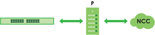
As of this writing, this setting only allows communication between the Switch and the NCC.
The following table describes the labels in this screen.
label | description |
|---|---|
Active | Enable the switch button to enable communication between the Switch and NCC through a proxy server. |
Server | Enter the IP address (dotted decimal notation) or host name of the proxy server. When entering the host name, up to 128 alphanumeric characters are allowed for the Server except [ ? ], [ | ], [ ' ], or [ " ]. |
Port | Enter the port number of the proxy server (1 – 65535). |
Authentication | Enable the switch button to enable proxy server authentication using a Username and Password. |
Username | Enter a login user name from the proxy server administrator. Up to 32 alphanumeric characters are allowed for the Username. The string should not contain [ ? ], [ | ], [ ' ], [ " ], [ , ], [ : ], or space. |
Password | Enter a login password from the proxy server administrator. Up to 32 alphanumeric characters are allowed for the Password except [ ? ], [ | ], [ ' ], and [ " ]. |
Apply | Click Apply to save your changes to the Switch’s run-time memory. The Switch loses these changes if it is turned off or loses power, so use the Save link on the top navigation panel to save your changes to the non-volatile memory when you are done configuring. |
Cancel | Click Cancel to reset the fields to your previous configuration. |
IPv6 Overview
This chapter introduces the IPv6 screens.
IPv6 Status
The following table describes the labels in this screen.
label | description |
|---|---|
Domain Name Server | |
Domain Name Server | This field displays the IP address of the DNS server. |
Source | This field displays whether the DNS server address is configured manually (Static) or obtained automatically using DHCPv6. |
IPv6 Table | |
Index | This field displays the index number of an IPv6 interface. Click on an index number to view more interface details. |
Interface | This is the name of the IPv6 interface you created. |
Active | This field displays whether the IPv6 interface is activated or not. |
IPv6 Interface Status Details
Use this screen to view a specific IPv6 interface status and detailed information.
The following table describes the labels in this screen.
label | description |
|---|---|
Static IPv6 Active This field displays whether the IPv6 interface is activated or not. | |
MTU Size | This field displays the Maximum Transmission Unit (MTU) size for IPv6 packets on this interface. |
ICMPv6 Rate Limit Bucket Size | This field displays the maximum number of ICMPv6 error messages which are allowed to transmit in a given time interval. If the bucket is full, subsequent error messages are suppressed. |
ICMPv6 Rate Limit Error Interval | This field displays the time period (in milliseconds) during which ICMPv6 error messages of up to the bucket size can be transmitted. 0 means no limit. |
ND DAD Active | This field displays whether Neighbor Discovery (ND) Duplicate Address Detection (DAD) is enabled on the interface. |
Number of DAD Attempts | This field displays the number of consecutive neighbor solicitations the Switch sends for this interface. |
NS-Interval (millisecond) | This field displays the time interval (in milliseconds) at which neighbor solicitations are re-sent for this interface. |
ND Reachable Time (millisecond) | This field displays how long (in milliseconds) a neighbor is considered reachable for this interface. |
Stateless Address Autoconfig | This field displays whether the Switch’s interface can automatically generate a link-local address through stateless auto-configuration. |
Link-Local Address | This field displays the Switch’s link-local IP address and prefix generated by the interface. It also shows whether the IP address is preferred, which means it is a valid address and can be used as a sender or receiver address. |
Global Unicast Address | This field displays the Switch’s global unicast address to identify this interface. |
Joined Group Address | This field displays the IPv6 multicast addresses of groups the Switch’s interface joins. |
DHCPv6 Client Active This field displays whether the Switch acts as a DHCPv6 client to get an IPv6 address from a DHCPv6 server. | |
Identity Association An Identity Association (IA) is a collection of addresses assigned to a DHCP client, through which the server and client can manage a set of related IP addresses. Each IA must be associated with exactly one interface. | |
IA Type | The IA type is the type of address in the IA. Each IA holds one type of address. IA_NA means an identity association for non-temporary addresses and IA_TA is an identity association for temporary addresses. |
IAID | Each IA consists of a unique IAID and associated IP information. |
T1 | This field displays the DHCPv6 T1 timer. After T1, the Switch sends the DHCPv6 server a Renew message. An IA_NA option contains the T1 and T2 fields, but an IA_TA option does not. The DHCPv6 server uses T1 and T2 to control the time at which the client contacts with the server to extend the lifetimes on any addresses in the IA_NA before the lifetimes expire. |
T2 | This field displays the DHCPv6 T2 timer. If the time T2 is reached and the server does not respond, the Switch sends a Rebind message to any available server. |
State | This field displays the state of the TA. It shows Active when the Switch obtains addresses from a DHCpv6 server and the TA is created. Renew when the TA’s address lifetime expires and the Switch sends out a Renew message. Rebind when the Switch does not receive a response from the original DHCPv6 server and sends out a Rebind message to another DHCPv6 server. |
SID | This field displays the DHCPv6 server’s unique ID. |
Address | This field displays the Switch’s global address which is assigned by the DHCPv6 server. |
Preferred Lifetime | This field displays how long (in seconds) that the global address remains preferred. |
Valid Lifetime | This field displays how long (in seconds) that the global address is valid. |
DNS | This field displays the DNS server address assigned by the DHCPv6 server. |
Domain List | This field displays the address record when the Switch queries the DNS server to resolve domain names. |
Restart DHCPv6 Client | Click Restart to send a new DHCP request to the DHCPv6 server and update the IPv6 address and DNS information for this interface. |
IPv6 Global Setup
Use this screen to configure the global IPv6 settings.
The following table describes the labels in this screen.
label | description |
|---|---|
IPv6 Hop Limit | Specify the maximum number of hops (from 1 to 255) in router advertisements. This is the maximum number of hops on which an IPv6 packet is allowed to transmit before it is discarded by an IPv6 router, which is similar to the TTL field in IPv4. |
ICMPv6 Rate Limit Bucket Size | Specify the maximum number of ICMPv6 error messages (from 1 to 200) which are allowed to transmit in a given time interval. If the bucket is full, subsequent error messages are suppressed. |
ICMPv6 Rate Limit Error Interval | Specify the time period (from 0 to 2147483647 milliseconds) during which ICMPv6 error messages of up to the bucket size can be transmitted. 0 means no limit. |
Apply | Click Apply to save your changes to the Switch’s run-time memory. The Switch loses these changes if it is turned off or loses power, so use the Save link on the top navigation panel to save your changes to the non-volatile memory when you are done configuring. |
Cancel | Click Cancel to begin configuring this screen afresh. |
Clear | Click Clear to reset the fields to the factory defaults. |
IPv6 Interface Setup
Use this screen to view and configure an IPv6 interface you create in the SYSTEM > Interface Setup screen.
The following table describes the labels in this screen.
label | description |
|---|---|
Index | This is the interface index number. |
Interface | This is the name of the IPv6 interface you created. |
Active | This field displays whether the IPv6 interface is activated or not. |
Address Autoconfig | This field displays whether stateless auto-configuration is enabled on the interface. |
Select an entry’s checkbox to select a specific entry. | |
Edit | Click Edit to edit the selected interface. |
Edit an IPv6 Interface
Use this screen to turn on or off an IPv6 interface you create in the SYSTEM > Interface Setup > Interface Setup screen.
The following table describes the labels in this screen.
label | description |
|---|---|
Interface | Select the IPv6 interface you want to configure. |
Active | Enable the switch button to enable the interface. |
Address Autoconfig | Select this option to allow the interface to automatically generate a link-local address through stateless auto-configuration. |
Apply | Click Apply to save your changes to the Switch’s run-time memory. The Switch loses these changes if it is turned off or loses power, so use the Save link on the top navigation panel to save your changes to the non-volatile memory when you are done configuring. |
Clear | Click Clear to clear the fields to the factory defaults. |
Cancel | Click Cancel to not save the configuration you make and return to the last screen. |
IPv6 Link-Local Address Setup
A link-local address uniquely identifies a device on the local network (the LAN). It is similar to a “private IP address” in IPv4. You can have the same link-local address on multiple interfaces on a device. A link-local unicast address has a predefined prefix of fe80::/10.
Use this screen to view and configure the interface’s link-local address and default gateway.
The following table describes the labels in this screen.
label | description |
|---|---|
Index | This is the interface index number. |
Interface | This is the name of the IPv6 interface you created. |
IPv6 Link-Local Address | This is the static IPv6 link-local address for the interface. |
IPv6 Default Gateway | This is the default gateway IPv6 address for the interface. |
Select an entry’s checkbox to select a specific entry. | |
Edit | Click Edit to edit the selected entry. |
Edit an IPv6 Link-Local Address
Use this screen to configure the link-local address and default gateway of an IPv6 interface you create in the SYSTEM > Interface Setup screen. Select an entry and click Edit in the SYSTEM > IPv6 > IPv6 Addressing > IPv6 Link-Local Address Setup screen to display this screen.
The following table describes the labels in this screen.
label | description |
|---|---|
Interface | Select the IPv6 interface you want to configure. |
Link-Local Address | Manually configure a static IPv6 link-local address for the interface. |
Default Gateway | Set the default gateway IPv6 address for the interface. When an interface cannot find a routing information for a frame’s destination, it forwards the packet to the default gateway. |
Apply | Click Apply to save your changes to the Switch’s run-time memory. The Switch loses these changes if it is turned off or loses power, so use the Save link on the top navigation panel to save your changes to the non-volatile memory when you are done configuring. |
Clear | Click Clear to clear the fields to the factory defaults. |
Cancel | Click Cancel to not save the configuration you make and return to the last screen. |
IPv6 Global Address Setup
Use this screen to view and configure the interface’s IPv6 global address.
The following table describes the labels in this screen.
label | description |
|---|---|
IPv6 Domain Name Server | |
Domain Name Server 1/2 | Enter a domain name server IPv6 address in order to be able to use a domain name instead of an IP address. |
Apply | Click Apply to save your changes to the Switch’s run-time memory. The Switch loses these changes if it is turned off or loses power, so use the Save link on the top navigation panel to save your changes to the non-volatile memory when you are done configuring. |
Cancel | Click this to reset the Domain Name Server values in this screen to their last-saved values. |
IPv6 Global Address Setup | |
Index | This is the interface index number. |
Interface | This is the name of the IPv6 interface you created. |
IPv6 Global Address/Prefix Length | This field displays the IPv6 global address and prefix length for the interface. |
EUI-64 | This shows whether the interface ID of the global address is generated using the EUI-64 format. |
Select an entry’s checkbox to select a specific entry. Otherwise, select the checkbox in the table heading row to select all entries. | |
Add/Edit | Click Add/Edit to add a new entry or edit a selected one. |
Delete | Click Delete to remove the selected entries. |
Add/Edit an IPv6 Global Address
Use this screen to configure the interface’s IPv6 global address. Click Add/Edit, or select an entry and click Add/Edit in the SYSTEM > IPv6 > IPv6 Addressing > IPv6 Global Address Setup screen to display this screen.
The following table describes the labels in this screen.
label | description |
|---|---|
Interface | Select the IPv6 interface you want to configure. |
IPv6 Global Address | Manually configure a static IPv6 global address for the interface. |
Prefix Length | Specify an IPv6 prefix length that specifies how many most significant bits (start from the left) in the address compose the network address. |
EUI-64 | Select this option to have the interface ID be generated automatically using the EUI-64 format. |
Apply | Click Apply to save your changes to the Switch’s run-time memory. The Switch loses these changes if it is turned off or loses power, so use the Save link on the top navigation panel to save your changes to the non-volatile memory when you are done configuring. |
Clear | Click Clear to clear the fields to the factory defaults. |
Cancel | Click Cancel to not save the configuration you make and return to the last screen. |
IPv6 Neighbor Discovery Setup
Use this screen to configure neighbor discovery settings for each interface.
The following table describes the labels in this screen.
label | description |
|---|---|
Index | This is the interface index number. |
Interface | This is the name of the IPv6 interface you created. |
DAD Attempts | This field displays the number of consecutive neighbor solicitations the Switch sends for this interface. |
NS Interval | This field displays the time interval (in milliseconds) at which neighbor solicitations are re-sent for this interface. |
Reachable Time | This field displays how long (in milliseconds) a neighbor is considered reachable for this interface. |
Select an entry’s checkbox to select a specific entry. | |
Edit | Click Edit to edit the selected entry. |
Edit an IPv6 Neighbor Discovery
Use this screen to configure neighbor discovery settings for each interface. Select an entry and click Edit in the SYSTEM > IPv6 > IPv6 Neighbor Discovery > IPv6 Neighbor Discovery Setup screen to display this screen.
The following table describes the labels in this screen.
label | description |
|---|---|
Interface | Select the IPv6 interface you want to configure. |
DAD Attempts | The Switch uses Duplicate Address Detection (DAD) with neighbor solicitation and advertisement messages to check whether an IPv6 address is already in use before assigning it to an interface. Specify the number of consecutive neighbor solicitations (from 0 to 600) the Switch sends for this interface. Enter 0 to turn off DAD. |
NS Interval | Specify the time interval (from 1000 to 3600000 milliseconds) at which neighbor solicitations are re-sent for this interface. |
Reachable Time | Specify how long (from 1000 to 3600000 milliseconds) a neighbor is considered reachable for this interface. |
Apply | Click Apply to save your changes to the Switch’s run-time memory. The Switch loses these changes if it is turned off or loses power, so use the Save link on the top navigation panel to save your changes to the non-volatile memory when you are done configuring. |
Clear | Click Clear to clear the fields to the factory defaults. |
Cancel | Click Cancel to not save the configuration you make and return to the last screen. |
IPv6 Neighbor Setup
Use this screen to view and configure static IPv6 neighbor entries in the Switch’s IPv6 neighbor table to store the neighbor information permanently.
The following table describes the labels in this screen.
label | description |
|---|---|
Index | This is the interface index number. |
Interface | This is the name of the IPv6 interface you created. |
Neighbor Address | This field displays the IPv6 address of the neighboring device which can be reached through the interface. |
MAC | This field displays the MAC address of the neighboring device which can be reached through the interface. |
Select an entry’s checkbox to select a specific entry. Otherwise, select the checkbox in the table heading row to select all entries. | |
Add/Edit | Click Add/Edit to add a new entry or edit a selected one. |
Delete | Click Delete to remove the selected entries. |
Add/Edit IPv6 Neighbor
Use this screen to create a static IPv6 neighbor entry. Click Add/Edit, or select an entry and click Add/Edit in the SYSTEM > IPv6 > IPv6 Neighbor Setup > IPv6 Neighbor Setup screen to display this screen.
The following table describes the labels in this screen.
label | description |
|---|---|
Interface | Select the type of IPv6 interface for which you want to configure. The Switch supports the VLAN interface type for IPv6 at the time of writing. |
Interface ID | Specify a unique identification number (from 1 to 4094) for the interface. A static IPv6 neighbor entry displays in the MONITOR > IPv6 Neighbor Table > IPv6 Neighbor Table screen only when the interface ID is also created in the SYSTEM > Interface Setup > Interface Setup screen. To have IPv6 function properly, you should configure a static VLAN with the same ID number in the SWITCHING > VLAN screens. |
Neighbor Address | Specify the IPv6 address of the neighboring device which can be reached through the interface. |
MAC | Specify the MAC address of the neighboring device which can be reached through the interface. |
Apply | Click Apply to save your changes to the Switch’s run-time memory. The Switch loses these changes if it is turned off or loses power, so use the Save link on the top navigation panel to save your changes to the non-volatile memory when you are done configuring. |
Clear | Click Clear to clear the fields to the factory defaults. |
Cancel | Click Cancel to not save the configuration you make and return to the last screen. |
DHCPv6 Client Setup
Use this screen to configure the Switch’s DHCP settings when it is acting as a DHCPv6 client.
The following table describes the labels in this screen.
label | description |
|---|---|
Index | This is the interface index number. |
Interface | This is the name of the IPv6 interface you created. |
IA-NA | This field displays whether the Switch obtains a non-temporary IP address from the DHCPv6 server. |
Rapid-Commit | This field displays whether the Switch obtains information from the DHCPv6 server by a rapid two-message exchange. |
DNS | This field displays whether the Switch obtains DNS server IPv6 addresses from the DHCPv6 server. |
Domain-List | This field displays whether the Switch obtains a list of domain names from the DHCP server. |
Information Refresh Minimum | This field displays the time interval (in seconds) at which the Switch exchanges other configuration information with a DHCPv6 server again. |
Select an entry’s checkbox to select a specific entry. | |
Edit | Click Edit to edit the selected entry. |
Edit DHCPv6 Client
Use this screen to configure the Switch’s DHCP settings when it is acting as a DHCPv6 client. Select an entry and click Edit in the SYSTEM > IPv6 > DHCPv6 Client Setup > DHCPv6 Client Setup screen to display this screen.
The following table describes the labels in this screen.
label | description |
|---|---|
Interface | Select the IPv6 interface you want to configure. |
IA Type | Select IA-NA to set the Switch to get a non-temporary IP address from the DHCPv6 server for this interface. Optionally, you can also select Rapid-Commit to have the Switch send its DHCPv6 Solicit message with a Rapid Commit option to obtain information from the DHCPv6 server by a rapid two-message exchange. The Switch discards any Reply messages that do not include a Rapid Commit option. The DHCPv6 server should also support the Rapid Commit option to have it work well. |
Options | Select DNS to have the Switch obtain DNS server IPv6 addresses and/or select Domain-List to have the Switch obtain a list of domain names from the DHCP server. |
Information Refresh Minimum | Specify the time interval (from 600 to 4294967295 seconds) at which the Switch exchanges other configuration information with a DHCPv6 server again. |
Apply | Click Apply to save your changes to the Switch’s run-time memory. The Switch loses these changes if it is turned off or loses power, so use the Save link on the top navigation panel to save your changes to the non-volatile memory when you are done configuring. |
Clear | Click Clear to clear the fields to the factory defaults. |
Cancel | Click Cancel to not save the configuration you make and return to the last screen. |
Login
Up to five people (one administrator and four non-administrators) may access the Switch through Web Configurator at any one time.
• An administrator is someone who can both view and configure Switch changes. The default user name for the Administrator is admin. The default administrator password is 1234.
• A non-administrator (user name is something other than admin) is someone who can view and/or configure Switch settings. The configuration right varies depending on the user’s privilege level.
The following table describes the labels in this screen.
LABEL | Description |
|---|---|
Administrator This is the default administrator account with the “admin” user name. You can change the default administrator user name. | |
User Name | Change the default “admin” system user name (up to 32 printable ASCII characters except [ ? ], [ | ], [ ' ], [ " ], [ space ], [ , ], or [ : ]. |
Old Password | Enter the existing system password (1234 is the default password). |
New Password | Enter your new system password. The password rules are: • 4 to 32 characters in length • [ ? ], [ | ], [ ' ], [ " ], [ , ], [ [ ], [ ] ] and space are not allowed |
Retype to confirm | Retype your new system password for confirmation. You can enter up to 32 printable ASCII characters. |
Edit Logins You may configure passwords for up to four users. These users can have read-only or read/write access. | |
Login | This is the index of an user account. |
User Name | Specify the user name (up to 32 printable ASCII characters except [ ? ], [ | ], [ ' ], [ " ], [ space ], [ , ], or [ : ]). |
Password | Enter your new system password. The password rules are: • 4 to 32 characters in length • [ ? ], [ | ], [ ' ], [ " ], [ , ], [ [ ], [ ] ] and space are not allowed |
Retype to confirm | Retype your new system password for confirmation. |
Privilege | Type the privilege level for this user. At the time of writing, users may have a privilege level of 0, 3, 13, or 14 representing different configuration rights as shown below. • 0 – Display basic system information. • 3 – Display configuration or status. • 13 – Configure features except for login accounts, SNMP user accounts, the authentication method sequence and authorization settings, multiple logins, administrator and enable passwords, and configuration information display. • 14 – Configure login accounts, SNMP user accounts, the authentication method sequence and authorization settings, multiple logins, and administrator and enable passwords, and display configuration information. Users can run command lines if the session’s privilege level is greater than or equal to the command’s privilege level. The session privilege initially comes from the privilege of the login account. For example, if the user has a privilege of 5, he or she can run commands that requires privilege level of 5 or less but not more. |
Apply | Click Apply to save your changes to the Switch’s run-time memory. The Switch loses these changes if it is turned off or loses power, so use the Save link on the top navigation panel to save your changes to the non-volatile memory when you are done configuring. |
Cancel | Click Cancel to begin configuring this screen afresh. |
SNMP Overview
This chapter introduces the SNMP screens and shows you how to setup SNMP settings for management.
Configure SNMP
Use this screen to configure your SNMP settings.
The following table describes the labels in this screen.
LABEL | Description |
|---|---|
General Setting Use this section to specify the SNMP version and community (password) values. | |
Version | Select the SNMP version for the Switch. The SNMP version on the Switch must match the version on the SNMP manager. Choose SNMP version 2c (v2c), SNMP version 3 (v3) or both (v3v2c). SNMP version 2c is backwards compatible with SNMP version 1. |
Get Community | Enter the Get Community string, which is the password for the incoming Get- and GetNext- requests from the management station. The Get Community string is only used by SNMP managers using SNMP version 2c or lower. |
Set Community | Enter the Set Community string, which is the password for incoming Set- requests from the management station. The Set Community string is only used by SNMP managers using SNMP version 2c or lower. |
Trap Community | Enter the Trap Community string, which is the password sent with each trap to the SNMP manager. The Trap Community string is only used by SNMP managers using SNMP version 2c or lower. |
Trap Destination Use this section to configure where to send SNMP traps from the Switch. | |
Index | This is the index of a trap destination. |
Version | Specify the version of the SNMP trap messages. |
IP | Enter the IP addresses of up to four managers to send your SNMP traps to. |
Port | Enter the port number upon which the manager listens for SNMP traps. |
Username | Enter the user name to be sent to the SNMP manager along with the SNMP v3 trap. The string should not contain [ ? ], [ | ], [ ' ], [ " ], [ , ], [ : ], or space. This user name must match an existing account on the Switch (configured in the SYSTEM > SNMP > SNMP User screen). |
Apply | Click Apply to save your changes to the Switch’s run-time memory. The Switch loses these changes if it is turned off or loses power, so use the Save link on the top navigation panel to save your changes to the non-volatile memory when you are done configuring. |
Cancel | Click Cancel to begin configuring this screen afresh. |
SNMP User
Use this screen to create SNMP users for authentication with managers using SNMP v3 and associate them to SNMP groups. An SNMP user is an SNMP manager.
The following table describes the labels in this screen.
LABEL | Description |
|---|---|
Index | This is a read-only number identifying a login account on the Switch. |
Username | This field displays the user name of a login account on the Switch. |
Security Level | This field displays whether you want to implement authentication and/or encryption for SNMP communication with this user. |
Authentication | This field displays the authentication algorithm used for SNMP communication with this user. |
Privacy | This field displays the encryption method used for SNMP communication with this user. |
Group | This field displays the SNMP group to which this user belongs. |
Select an entry’s checkbox to select a specific entry. Otherwise, select the checkbox in the table heading row to select all entries. | |
Add/Edit | Click Add/Edit to add a new entry or edit a selected one. |
Delete | Click Delete to remove the selected entries. |
Add/Edit SNMP User
Use this screen to create SNMP users for authentication with managers using SNMP v3 and associate them to SNMP groups. An SNMP user is an SNMP manager. Click Add/Edit, or select an entry and click Add/Edit in the SYSTEM > SNMP > SNMP User screen to view the screen.
The following table describes the labels in this screen.
LABEL | Description |
|---|---|
Username | Specify the user name (up to 32 printable ASCII characters) of a login account on the Switch. The string should not contain [ ? ], [ | ], [ ' ], [ " ], [ space ], [ , ], or [ : ]. |
Security Level | Select whether you want to implement authentication and/or encryption for SNMP communication from this user. Choose: • no auth – to use the user name as the password string to send to the SNMP manager. This is equivalent to the Get, Set and Trap Community in SNMP v2c. This is the lowest security level. • auth – to implement an authentication algorithm for SNMP messages sent by this user. • priv – to implement authentication and encryption for SNMP messages sent by this user. This is the highest security level. |
Authentication | Select an authentication algorithm. MD5 (Message Digest 5) and SHA (Secure Hash Algorithm) are hash algorithms used to authenticate SNMP data. SHA authentication is generally considered stronger than MD5, but is slower. |
Password | Enter the password of up to 32 printable ASCII characters (except [ ? ], [ | ], [ ' ], [ " ], [ space ], [ , ], [ [ ], or [ ] ]) for SNMP user authentication. |
Privacy | Specify the encryption method for SNMP communication from this user. You can choose one of the following: • DES – Data Encryption Standard is a widely used (but breakable) method of data encryption. It applies a 56-bit key to each 64-bit block of data. • AES – Advanced Encryption Standard is another method for data encryption that also uses a secret key. AES applies a 128-bit key to 128-bit blocks of data. |
Password | Enter the password of up to 32 printable ASCII characters (except [ ? ], [ | ], [ ' ], [ " ], [ space ], [ , ], [ [ ], or [ ] ]) for encrypting SNMP packets. |
Group | SNMP v3 adopts the concept of View-based Access Control Model (VACM) group. SNMP managers in one group are assigned common access rights to MIBs. Specify in which SNMP group this user is. admin – Members of this group can perform all types of system configuration, including the management of administrator accounts. read-write – Members of this group have read and write rights, meaning that the user can create and edit the MIBs on the Switch, except the user account and AAA configuration. read-only – Members of this group have read rights only, meaning the user can collect information from the Switch. |
Apply | Click Apply to save your changes to the Switch’s run-time memory. The Switch loses these changes if it is turned off or loses power, so use the Save link on the top navigation panel to save your changes to the non-volatile memory when you are done configuring. |
Clear | Click Clear to clear the fields to the factory defaults. |
Cancel | Click Cancel to not save the configuration you make and return to the last screen. |
SNMP Trap Group
Use this screen to specify the types of SNMP traps that should be sent to each SNMP manager.
The following table describes the labels in this screen.
LABEL | Description |
|---|---|
Trap Destination IP | Select one of your configured trap destination IP addresses. These are the IP addresses of the SNMP managers. You must first configure a trap destination IP address in the SYSTEM > SNMP > SNMP screen. Use the rest of the screen to select which traps the Switch sends to that SNMP manager. |
Options | Select the individual SNMP traps that the Switch is to send to the SNMP station. The traps are grouped by category. Selecting a category in the heading row automatically selects all of the SNMP traps under that category. Clear the checkboxes for individual traps that you do not want the Switch to send to the SNMP station. Clearing a category’s checkbox automatically clears all of the category’s trap checkboxes (the Switch only sends traps from selected categories). |
Apply | Click Apply to save your changes to the Switch’s run-time memory. The Switch loses these changes if it is turned off or loses power, so use the Save link on the top navigation panel to save your changes to the non-volatile memory when you are done configuring. |
Cancel | Click Cancel to begin configuring this screen afresh. |
SNMP Traps on a Port
Use this screen to set whether a trap received on the ports would be sent to the SNMP manager.
The following table describes the labels in this screen.
LABEL | Description |
|---|---|
Options | Select the trap type you want to configure here. |
Port | This field displays a port number. |
* | Settings in this row apply to all ports. Use this row only if you want to make some of the settings the same for all ports. Use this row first to set the common settings and then make adjustments on a port-by-port basis. Changes in this row are copied to all the ports as soon as you make them. |
Active | Select this checkbox to enable the trap type of SNMP traps on this port. The Switch sends the related traps received on this port to the SNMP manager. Clear this checkbox to disable the sending of SNMP traps on this port. |
Apply | Click Apply to save your changes to the Switch’s run-time memory. The Switch loses these changes if it is turned off or loses power, so use the Save link on the top navigation panel to save your changes to the non-volatile memory when you are done configuring. |
Cancel | Click Cancel to begin configuring this screen afresh. |
Switch Setup Overview
Use this screen to do the Switch’s basic setup configuration, for example, VLAN (Virtual Local Area Network) type, enabling switching protocols, and MAC learning aging time setup.
Switch Setup
The VLAN setup screens change depending on whether you choose 802.1Q or Port Based in the VLAN Type field in this screen.
The following table describes the labels in this screen.
label | description |
|---|---|
VLAN Type | Choose 802.1Q or Port Based. The SWITCHING > VLAN link and its sub-links only appears when you choose 802.1Q VLAN type in this screen. |
MAC Address Learning MAC address learning reduces outgoing traffic broadcasts. For MAC address learning to occur on a port, the port must be active. | |
Aging Time | Enter a time from 10 to 1000000 seconds. This is how long all dynamically learned MAC addresses remain in the MAC address table before they age out (and must be relearned). |
ARP Aging Time | |
Aging Time | Enter a time from 60 to 1000000 seconds. This is how long dynamically learned ARP entries remain in the ARP table before they age out (and must be relearned). The setting here applies to ARP entries which are newly added in the ARP table after you click Apply. |
Apply | Click Apply to save your changes to the Switch’s run-time memory. The Switch loses these changes if it is turned off or loses power, so use the Save link on the top navigation panel to save your changes to the non-volatile memory when you are done configuring. |
Cancel | Click Cancel to begin configuring this screen afresh. |
Syslog Overview
The syslog protocol allows devices to send event notification messages across an IP network to syslog servers that collect the event messages. A syslog-enabled device can generate a syslog message and send it to a syslog server.
Syslog is defined in RFC 3164. The RFC defines the packet format, content and system log related information of syslog messages. Each syslog message has a facility and severity level. The syslog facility identifies a file in the syslog server. Refer to the documentation of your syslog program for details. The following table describes the syslog severity levels.
code | severity |
|---|---|
0 | Emergency: The system is unusable. |
1 | Alert: Action must be taken immediately. |
2 | Critical: The system condition is critical. |
3 | Error: There is an error condition on the system. |
4 | Warning: There is a warning condition on the system. |
5 | Notice: There is a normal but significant condition on the system. |
6 | Informational: The syslog contains an informational message. |
7 | Debug: The message is intended for debug-level purposes. |
Syslog Setup
The syslog feature sends logs to an external syslog server. Use this screen to configure the device’s system logging settings and configure a list of external syslog servers.
The following table describes the labels in this screen.
label | description |
|---|---|
Syslog Setup | |
Active | Enable the switch button to turn on syslog (system logging) and then configure the syslog setting. |
Logging Type | This column displays the names of the categories of logs that the device can generate. |
Active | Select this option to set the device to generate logs for the corresponding category. |
Facility | The log facility allows you to send logs to different files in the syslog server. Refer to the documentation of your syslog program for more details. |
Apply | Click Apply to save your changes to the Switch’s run-time memory. The Switch loses these changes if it is turned off or loses power, so use the Save link on the top navigation panel to save your changes to the non-volatile memory when you are done configuring. |
Cancel | Click Cancel to begin configuring this screen afresh. |
Syslog Server Setup | |
Index | This is the index number of a syslog server entry. |
Active | This field displays if the device is activated to send logs to the syslog server. |
IP Address | This field displays the IP address of the syslog server. |
UDP Port | This field displays the port of the syslog server. |
Log Level | This field displays the severity level of the logs that the device is to send to this syslog server. |
Select an entry’s checkbox to select a specific entry. Otherwise, select the checkbox in the table heading row to select all entries. | |
Add/Edit | Click Add/Edit to add a new entry or edit a selected one. |
Delete | Click Delete to remove the selected entries. |
Add/Edit a Syslog Server
Use this screen to configure an external syslog server.
Click Add/Edit, or select an entry and click Add/Edit in the SYSTEM > Syslog Setup > Syslog Setup screen to display this screen.
The following table describes the labels in this screen.
label | description |
|---|---|
Active | Enable the switch button to have the device send logs to this syslog server. Clear the checkbox if you want to create a syslog server entry but not have the device send logs to it (you can edit the entry later). |
Server Address | Enter the IPv4 or IPv6 address of the syslog server. |
UDP Port | The default syslog server port is 514. If your syslog server uses a different port, configure the one it uses here. |
Log Level | Select the severity levels of the logs that you want the device to send to this syslog server. The lower the number, the more critical the logs are. |
Apply | Click Apply to save your changes to the Switch’s run-time memory. The Switch loses these changes if it is turned off or loses power, so use the Save link on the top navigation panel to save your changes to the non-volatile memory when you are done configuring. |
Clear | Click Clear to clear the fields to the factory defaults. |
Cancel | Click Cancel to not save the configuration you make and return to the last screen. |
Time Range Overview
You can set up one-time and recurring schedules for time-oriented features, such as PoE and classifier. The UAG supports one-time and recurring schedules. One-time schedules are effective only once, while recurring schedules usually repeat. Both types of schedules are based on the current date and time in the Switch.
The time range can be configured in two ways – Absolute and Periodic. Absolute is a fixed time range with a start and end time. Periodic is recurrence of a time range and does not have an end time.
Configure a Time Range
The following table describes the labels in this screen.
label | description |
|---|---|
Select an entry’s checkbox to select a specific entry. Otherwise, select the checkbox in the table heading row to select all entries. | |
Index | This field displays the index number of the rule. |
Name | This field displays the descriptive name for this rule. This is for identification purpose only. You can enter up to 32 printable ASCII characters except [ ? ], [ | ], [ ' ], [ " ], or [ , ]. |
Type | This displays the schedule type of the time range rule. Absolute An one-time schedule. One-time schedules begin on a specific start date and time and end on a specific stop date and time. One-time schedules are useful for long holidays and vacation periods. Periodic A recurring schedule. Recurring schedules begin at a specific start time and end at a specific stop time on selected days of the week (Sunday, Monday, Tuesday, Wednesday, Thursday, Friday, and Saturday). Recurring schedules are useful for defining the workday and off-work hours. |
Range | This field displays the time periods to which this schedule applies. |
Add/Edit | Click Add/Edit to add a new schedule rule or edit a selected one. |
Delete | Click Delete to remove the selected rules. |
Add/Edit Time Range
This screen allows you to create a new time range or edit an existing one.
To access this screen, click the Add/Edit button or select an entry from the list and click the Add/Edit button.
The following table describes the labels in this screen.
label | description |
|---|---|
Name | Enter a descriptive name for this rule for identifying purposes. The string should not contain [ ? ], [ | ], [ ' ], [ " ], or [ , ]. |
Type | Select Absolute to create a one-time schedule. One-time schedules begin on a specific start date and time and end on a specific stop date and time. One-time schedules are useful for long holidays and vacation periods. Alternatively, select Periodic to create a recurring schedule. Recurring schedules begin at a specific start time and end at a specific stop time on selected days of the week (Sunday, Monday, Tuesday, Wednesday, Thursday, Friday, and Saturday). Recurring schedules are useful for defining the workday and off-work hours. |
Absolute | This section is available only when you set Type to Absolute. |
Start | Specify the year, month, day, hour and minute when the schedule begins. |
End | Specify the year, month, day, hour and minute when the schedule ends. |
Periodic | This section is available only when you set Type to Periodic. Select the first option if you want to define a recurring schedule for a consecutive time period. You then select the day of the week, hour and minute when the schedule begins and ends respectively. Select the second option if you want to define a recurring schedule for multiple non-consecutive time periods. You need to select each day of the week the recurring schedule is effective. You also need to specify the hour and minute when the schedule begins and ends each day. The schedule begins and ends in the same day. |
Apply | Click Apply to save your changes to the Switch’s run-time memory. The Switch loses these changes if it is turned off or loses power, so use the Save link on the top navigation panel to save your changes to the non-volatile memory when you are done configuring. |
Clear | Click Clear to clear the fields to the factory defaults. |
Cancel | Click Cancel to not save the configuration you make and return to the last screen. |