SWITCHING
Layer 2 Protocol Tunneling Overview
This chapter shows you how to configure layer 2 protocol tunneling on the Switch.
What You Need to Know
Layer 2 protocol tunneling (L2PT) is used on the service provider's edge devices.
L2PT allows edge switches (1 and 2 in the following figure) to tunnel layer 2 STP (Spanning Tree Protocol), CDP (Cisco Discovery Protocol) and VTP (VLAN Trunking Protocol) packets between customer switches (A, B and C in the following figure) connected through the service provider’s network. The edge switch encapsulates layer 2 protocol packets with a specific MAC address before sending them across the service provider’s network to other edge switches.
Layer 2 Protocol Tunneling Network Scenario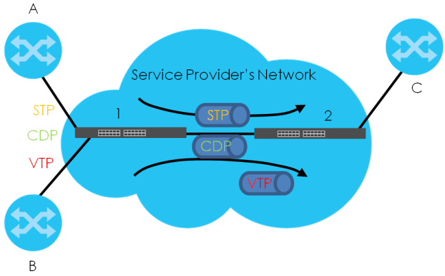
In the following example, if you enable L2PT for STP, you can have switches A, B, C and D in the same spanning tree, even though switch A is not directly connected to switches B, C and D. Topology change information can be propagated throughout the service provider’s network.
To emulate a point-to-point topology between two customer switches at different sites, such as A and B, you can enable protocol tunneling on edge switches 1 and 2 for PAgP (Port Aggregation Protocol), LACP or UDLD (Uni-Directional Link Detection).
L2PT Network Example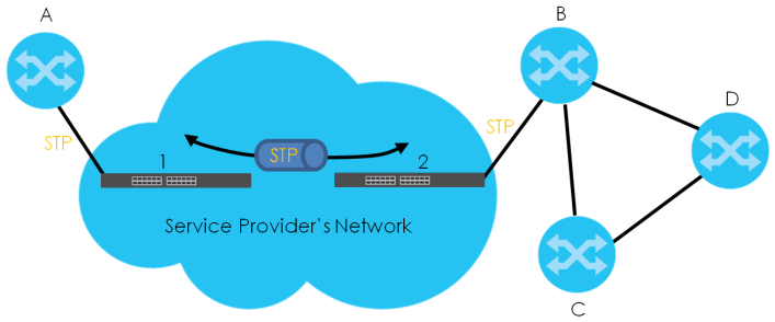
Layer 2 Protocol Tunneling Mode
Each port can have two layer 2 protocol tunneling modes, Access and Tunnel.
• The Access port is an ingress port on the service provider's edge device (1 or 2) and connected to a customer switch (A or B). Incoming layer 2 protocol packets received on an access port are encapsulated and forwarded to the tunnel ports.
• The Tunnel port is an egress port at the edge of the service provider's network and connected to another service provider’s switch. Incoming encapsulated layer 2 protocol packets received on a tunnel port are decapsulated and sent to an access port.
Configuring Layer 2 Protocol Tunneling
The following table describes the labels in this screen.
label | description |
|---|---|
Active | Enable the switch button to enable layer 2 protocol tunneling on the Switch. |
Destination MAC Address | Specify a MAC address with which the Switch uses to encapsulate the layer 2 protocol packets by replacing the destination MAC address in the packets. |
Port | This field displays the port number. * means all ports. |
* | Use this row to make the setting the same for all ports. Use this row first and then make adjustments on a port-by-port basis. |
CDP | Select this option to have the Switch tunnel CDP (Cisco Discovery Protocol) packets so that other Cisco devices can be discovered through the service provider’s network. |
STP | Select this option to have the Switch tunnel STP (Spanning Tree Protocol) packets so that STP can run properly across the service provider’s network and spanning trees can be set up based on bridge information from all (local and remote) networks. |
VTP | Select this option to have the Switch tunnel VTP (VLAN Trunking Protocol) packets so that all customer switches can use consistent VLAN configuration through the service provider’s network. |
LLDP | Select this option to have the Switch tunnel LLDP (Link Layer Discovery Protocol) packets so that all network devices can advertise its identity and capabilities through the service provider’s network. |
Point to Point | The Switch supports PAgP (Port Aggregation Protocol), LACP (Link Aggregation Control Protocol) and UDLD (UniDirectional Link Detection) tunneling for a point-to-point topology. Both PAgP and UDLD are Cisco’s proprietary data link layer protocols. PAgP is similar to LACP and used to set up a logical aggregation of Ethernet ports automatically. UDLD is to determine the link’s physical status and detect a unidirectional link. |
PAGP | Select this option to have the Switch send PAgP packets to a peer to automatically negotiate and build a logical port aggregation. |
LACP | Select this option to have the Switch send LACP packets to a peer to dynamically create and manage trunk groups. |
UDLD | Select this option to have the Switch send UDLD packets to a peer’s port it connected to monitor the physical status of a link. |
Mode | Select Access to have the Switch encapsulate the incoming layer 2 protocol packets and forward them to the tunnel ports. Select Access for ingress ports at the edge of the service provider's network. Select Tunnel for egress ports at the edge of the service provider's network. The Switch decapsulates the encapsulated layer 2 protocol packets received on a tunnel port by changing the destination MAC address to the original one, and then forward them to an access port. If the services is not enabled on an access port, the protocol packets are dropped. |
Apply | Click Apply to save your changes to the Switch’s run-time memory. The Switch loses these changes if it is turned off or loses power, so use the Save link on the top navigation panel to save your changes to the non-volatile memory when you are done configuring. |
Cancel | Click Cancel to begin configuring this screen afresh. |
Loop Guard Overview
Loop guard allows you to configure the Switch to shut down a port if it detects that packets sent out on that port loop back to the Switch. While you can use Spanning Tree Protocol (STP) to prevent loops in the core of your network. STP cannot prevent loops that occur on the edge of your network.
Loop Guard vs. STP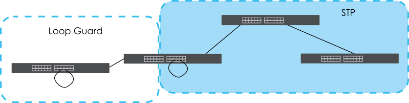
Loop guard is designed to handle loop problems on the edge of your network. This can occur when a port is connected to a Switch that is in a loop state. Loop state occurs as a result of human error. It happens when two ports on a switch are connected with the same cable. When a switch in loop state sends out broadcast messages the messages loop back to the switch and are re-broadcast again and again causing a broadcast storm.
If a switch (not in loop state) connects to a switch in loop state, then it will be affected by the switch in loop state in the following way:
• will receive broadcast messages sent out from the switch in loop state.
• will receive its own broadcast messages that it sends out as they loop back. It will then re-broadcast those messages again.
Loop Guard Setup
The following table describes the labels in this screen.
label | description |
|---|---|
Active | Enable the switch button to activate loop guard function on the Switch. The Switch generates syslog, internal log messages as well as SNMP traps when it shuts down a port through the loop guard feature. |
Port | This field displays the port number. |
* | Settings in this row apply to all ports. Use this row only if you want to make some settings the same for all ports. Use this row first to set the common settings and then make adjustments on a port-by-port basis. |
Active | Select this checkbox to enable the loop guard feature on this port. The Switch sends broadcast and multicast probe packets from this port to check if the switch it is connected to is in loop state. If the switch that this port is connected is in loop state the Switch will shut down this port. Clear this checkbox to disable the loop guard feature. |
Apply | Click Apply to save your changes to the Switch’s run-time memory. The Switch loses these changes if it is turned off or loses power, so use the Save link on the top navigation panel to save your changes to the non-volatile memory when you are done configuring. |
Cancel | Click Cancel to begin configuring this screen afresh. |
Mirroring Overview
Port mirroring allows you to copy a traffic flow to a monitor port (the port you copy the traffic to) in order that you can examine the traffic from the monitor port without interference.
Port Mirroring Setup
Use this screen to select a monitor port and specify the traffic flow to be copied to the monitor port.
The following table describes the labels in this screen.
LABEL | DESCRIPTION |
|---|---|
Active | Enable the switch button to activate port mirroring on the Switch. Disable the switch to disable the feature. |
Monitor Port | The monitor port is the port you copy the traffic to in order to examine it in more detail without interfering with the traffic flow on the original ports. Enter the port number of the monitor port. |
Port | This field displays the port number. |
* | Settings in this row apply to all ports. Use this row only if you want to make some settings the same for all ports. Use this row first to set the common settings and then make adjustments on a port-by-port basis. |
Mirrored | Select this option to mirror the traffic on a port. |
Direction | Specify the direction of the traffic to mirror by selecting from the drop-down list box. Choices are Egress (outgoing), Ingress (incoming) and Both. |
Apply | Click Apply to save your changes to the Switch’s run-time memory. The Switch loses these changes if it is turned off or loses power, so use the Save link on the top navigation panel to save your changes to the non-volatile memory when you are done configuring. |
Cancel | Click Cancel to reset the fields. |
Multicast Overview
Traditionally, IP packets are transmitted in one of either two ways – Unicast (one sender to one recipient) or Broadcast (one sender to everybody on the network). Multicast delivers IP packets to just a group of hosts on the network.
IGMP (Internet Group Management Protocol) is a network-layer protocol used to establish membership in a multicast group – it is not used to carry user data. Refer to RFC 1112, RFC 2236 and RFC 3376 for information on IGMP versions 1, 2 and 3 respectively.
IP Multicast Addresses
In IPv4, a multicast address allows a device to send packets to a specific group of hosts (multicast group) in a different subnetwork. A multicast IP address represents a traffic receiving group, not individual receiving devices. IP addresses in the Class D range (224.0.0.0 to 239.255.255.255) are used for IP multicasting. Certain IP multicast numbers are reserved by IANA for special purposes (see the IANA website for more information).
IGMP Snooping
A Switch can passively snoop on IGMP packets transferred between IP multicast routers or switches and IP multicast hosts to learn the IP multicast group membership. It checks IGMP packets passing through it, picks out the group registration information, and configures multicasting accordingly. IGMP snooping allows the Switch to learn multicast groups without you having to manually configure them.
The Switch forwards multicast traffic destined for multicast groups (that it has learned from IGMP snooping or that you have manually configured) to ports that are members of that group. IGMP snooping generates no additional network traffic, allowing you to significantly reduce multicast traffic passing through your Switch.
IGMP Snooping and VLANs
The Switch can perform IGMP snooping on up to 16 VLANs. You can configure the Switch to automatically learn multicast group membership of any VLANs. The Switch then performs IGMP snooping on the first 16 VLANs that send IGMP packets. This is referred to as auto mode. Alternatively, you can specify the VLANs that IGMP snooping should be performed on. This is referred to as fixed mode. In fixed mode the Switch does not learn multicast group membership of any VLANs other than those explicitly added as an IGMP snooping VLAN.
IPv4 Multicast Status
This screen shows the IPv4 multicast group information.
The following table describes the labels in this screen.
label | description |
|---|---|
Index | This is the index number of the entry. |
VID | This field displays the multicast VLAN ID. |
Port | This field displays the port number that belongs to the multicast group. |
Multicast Group | This field displays IP multicast group addresses. |
IGMP Snooping
The following table describes the labels in this screen.
label | description |
|---|---|
Active | Enable the switch button to enable IGMP Snooping to forward group multicast traffic only to ports that are members of that group. |
Querier | Select this to allow the Switch to send IGMP General Query messages to the VLANs with the multicast hosts attached. |
Report Proxy | Select this to allow the Switch to act as the IGMP report proxy and leave proxy. It will report group changes to a connected multicast router. The Switch not only checks IGMP packets between multicast routers or switches and multicast hosts to learn the multicast group membership, but also replaces the source MAC address in an IGMP v1/v2 report with its own MAC address before forwarding to the multicast router or switch. When the Switch receives more than one IGMP v1/v2 join report that requests to join the same multicast group, it only sends a new join report with its MAC address. This helps reduce the number of multicast join reports passed to the multicast router or switch. The Switch sends a leave message with its MAC address to the multicast router or switch only when it receives the leave message from the last host in a multicast group. |
Host Timeout | Specify the time (from 1 to 16711450) in seconds that elapses before the Switch removes an IGMP group membership entry if it does not receive report messages from the port. |
802.1p Priority | Select a priority level (0 – 7) to which the Switch changes the priority in outgoing IGMP control packets. Otherwise, select No-Change to not replace the priority. |
IGMP Filtering Active | Enable the switch button to enable IGMP filtering to control which IGMP groups a subscriber on a port can join. If you enable IGMP filtering, you must create and assign IGMP filtering profiles for the ports that you want to allow to join multicast groups. |
Unknown Multicast Frame | Specify the action to perform when the Switch receives an unknown multicast frame. • Select Flooding to send the frames to all ports. • Select Drop to discard the frames. • Select Drop on VLAN and enter the VLAN ID numbers to discard the frames on the specified VLANs. Use a dash to specify consecutive VLANs and a comma (no spaces) to specify non-consecutive VLANs. For example, 51–53 includes 51, 52 and 53, but 51,53 does not include 52. |
Unknown Multicast Frame to Querier Port | Specify the action to perform when Unknown Multicast Frame is set to Drop. • Select Drop to discard the frames. • Select Forwarding to send the frames to all querier ports. • Select Forwarding on VLAN and enter the VLAN ID numbers to send the frames to the ports which are used as an IGMP query port on the specified VLANs. Use a dash to specify consecutive VLANs and a comma (no spaces) to specify non-consecutive VLANs. For example, 51–53 includes 51, 52 and 53, but 51,53 does not include 52. |
Reserved Multicast Group | The IP address range of 224.0.0.0 to 224.0.0.255 are reserved for multicasting on the local network only. For example, 224.0.0.1 is for all hosts on a local network segment and 224.0.0.9 is used to send RIP routing information to all RIP v2 routers on the same network segment. A multicast router will not forward a packet with the destination IP address within this range to other networks. See the IANA web site for more information. The layer-2 multicast MAC addresses used by Cisco layer-2 protocols, 01:00:0C:CC:CC:CC and 01:00:0C:CC:CC:CD, are also included in this group. Specify the action to perform when the Switch receives a frame with a reserved multicast address. • Select Flooding to send the frames to all ports. • Select Drop to discard the frames. |
Use this section to configure IGMP Snooping on each port. | |
Port | This field displays the port number. |
* | Settings in this row apply to all ports. Use this row only if you want to make some settings the same for all ports. Use this row first to set the common settings and then make adjustments on a port-by-port basis. Changes in this row are copied to all the ports as soon as you make them. |
Immediate Leave | Select this to set the Switch to remove this port from the multicast tree when an IGMP version 2 leave message is received on this port. Select this option if there is only one host connected to this port. |
Normal Leave | Enter an IGMP normal leave timeout value (from 200 to 6348800) in miliseconds. Select this option to have the Switch use this timeout to update the forwarding table for the port. In normal leave mode, when the Switch receives an IGMP leave message from a host on a port, it forwards the message to the multicast router. The multicast router then sends out an IGMP Group-Specific Query (GSQ) message to determine whether other hosts connected to the port should remain in the specific multicast group. The Switch forwards the query message to all hosts connected to the port and waits for IGMP reports from hosts to update the forwarding table. This defines how many seconds the Switch waits for an IGMP report before removing an IGMP snooping membership entry when an IGMP leave message is received on this port from a host. |
Fast Leave | Enter an IGMP fast leave timeout value (from 200 to 6348800) in miliseconds. Select this option to have the Switch use this timeout to update the forwarding table for the port. In fast leave mode, right after receiving an IGMP leave message from a host on a port, the Switch itself sends out an IGMP Group-Specific Query (GSQ) message to determine whether other hosts connected to the port should remain in the specific multicast group. This helps speed up the leave process. This defines how many seconds the Switch waits for an IGMP report before removing an IGMP snooping membership entry when an IGMP leave message is received on this port from a host. |
Group Limited | Select this option to limit the number of multicast groups this port is allowed to join. |
Max Group Number | Enter the number of multicast groups this port is allowed to join. Once a port is registered in the specified number of multicast groups, any new IGMP join report frames is dropped on this port. |
Throttling | IGMP throttling controls how the Switch deals with the IGMP reports when the maximum number of the IGMP groups a port can join is reached. Select Deny to drop any new IGMP join report received on this port until an existing multicast forwarding table entry is aged out. Select Replace to replace an existing entry in the multicast forwarding table with the new IGMP reports received on this port. |
IGMP Filtering Profile | Select the name of the IGMP filtering profile to use for this port. Otherwise, select Default to prohibit the port from joining any multicast group. You can create IGMP filtering profiles in the SWITCHING > Multicast > IPv4 Multicast > IGMP Filtering Profile screen. |
IGMP Querier Mode | The Switch treats an IGMP query port as being connected to an IGMP multicast router (or server). The Switch forwards IGMP join or leave packets to an IGMP query port. Select Auto to have the Switch use the port as an IGMP query port if the port receives IGMP query packets. Select Fixed to have the Switch always use the port as an IGMP query port. Select this when you connect an IGMP multicast server to the port. Select Edge to stop the Switch from using the port as an IGMP query port. The Switch will not keep any record of an IGMP router being connected to this port. The Switch does not forward IGMP join or leave packets to this port. |
Apply | Click Apply to save your changes to the Switch’s run-time memory. The Switch loses these changes if it is turned off or loses power, so use the Save link on the top navigation panel to save your changes to the non-volatile memory when you are done configuring. |
Cancel | Click Cancel to begin configuring this screen afresh. |
IGMP Snooping VLAN
The following table describes the labels in this screen.
label | description |
|---|---|
IGMP Snooping VLAN | |
Mode | Select auto to have the Switch learn multicast group membership information of any VLANs automatically. Select fixed to have the Switch only learn multicast group membership information of the VLANs that you specify below. In either auto or fixed mode, the Switch can learn up to 16 VLANs. The Switch drops any IGMP control messages which do not belong to these 16 VLANs. You must also enable IGMP snooping in the SWITCHING > Multicast > IPv4 Multicast > IGMP Snooping screen first. |
Apply | Click Apply to save your changes to the Switch’s run-time memory. The Switch loses these changes if it is turned off or loses power, so use the Save link on the top navigation panel to save your changes to the non-volatile memory when you are done configuring. |
Cancel | Click Cancel to begin configuring this screen afresh. |
VLAN Use this section of the screen to add VLANs on which the Switch is to perform IGMP snooping. | |
Index | This is the index number of the IGMP snooping VLAN entry in the table. |
Name | This field displays the descriptive name for this VLAN group. |
VID | This field displays the ID number of the VLAN group. |
Select an entry’s checkbox to select a specific entry. Otherwise, select the checkbox in the table heading row to select all entries. | |
Add/Edit | Click Add/Edit to create a new entry or edit a selected one. |
Delete | Click Delete to remove the selected entries. |
Add/Edit IGMP Snooping VLANs
This screen allows you to add an IGMP snooping VLAN or edit an existing one.
To access this screen, click the Add/Edit button or select an entry from the list and click the Add/Edit button.
The following table describes the labels in this screen.
label | description |
|---|---|
Name | Enter the descriptive name of the VLAN for identification purposes. You can enter up to 32 printable ASCII characters except [ ? ], [ | ], [ ' ], [ " ] or [ , ]. |
VID | Enter the ID of a static VLAN; the valid range is between 1 and 4094. |
Apply | Click Apply to save your changes to the Switch’s run-time memory. The Switch loses these changes if it is turned off or loses power, so use the Save link on the top navigation panel to save your changes to the non-volatile memory when you are done configuring. |
Clear | Click Clear to clear the fields to the factory defaults. |
Cancel | Click Cancel to not save the configuration you make and return to the last screen. |
IGMP Filtering Profile
An IGMP filtering profile specifies a range of multicast groups that clients connected to the Switch are able to join. A profile contains a range of multicast IP addresses which you want clients to be able to join. Profiles are assigned to ports (in the IGMP Snooping screen). Clients connected to those ports are then able to join the multicast groups specified in the profile. Each port can be assigned a single profile. A profile can be assigned to multiple ports.
The following table describes the labels in this screen.
label | description |
|---|---|
Profile Name | This field displays the descriptive name of the profile. |
Start Address | This field displays the start of the multicast address range. |
End Address | This field displays the end of the multicast address range. |
Select an entry’s checkbox to select a specific entry. Otherwise, select the checkbox in the table heading row to select all entries. | |
Add Profile | Click this to add a new IGMP filtering profile. |
Add Rule | Click Add Rule to add a new rule and specify the profile it belongs to in the Add Rule screen. You can also select a profile entry and click Add Rule to add an additional rule for the selected profile. |
Delete | Select a profile and click Delete to remove the selected profile and the accompanying rules. Select a rule from a profile and click Delete to remove the selected rule. |
Add IGMP Filtering Profile
To access this screen, click the Add Profile button in the SWITCHING > Multicast > IPv4 Multicast > IGMP Filtering Profile screen.
The following table describes the labels in this screen.
label | description |
|---|---|
Profile Name | Enter a descriptive name for the profile for identification purposes. You can enter up to 32 printable ASCII characters except [ ? ], [ | ], [ ' ], [ " ] or [ , ]. |
Start Address | Enter the starting multicast IP address for a range of multicast IP addresses that you want to belong to the IGMP filter profile. |
End Address | Enter the ending multicast IP address for a range of IP addresses that you want to belong to the IGMP filter profile. If you want to add a single multicast IP address, enter it in both the Start Address and End Address fields. |
Apply | Click Apply to save your changes to the Switch’s run-time memory. The Switch loses these changes if it is turned off or loses power, so use the Save link on the top navigation panel to save your changes to the non-volatile memory when you are done configuring. |
Clear | Click Clear to clear the fields to the factory defaults. |
Cancel | Click Cancel to not save the configuration you make and return to the last screen. |
Add IGMP Filtering Rule
Click Add Rule in the SWITCHING > Multicast > IPv4 Multicast > IGMP Filtering Profile screen to access this screen.
The following table describes the labels in this screen.
label | description |
|---|---|
Profile Name | Select a profile from the drop-down list to add a additional rule for the existing profile. |
Start Address | Enter the starting multicast IP address for a range of multicast IP addresses that you want to belong to the IGMP filter profile. |
End Address | Enter the ending multicast IP address for a range of IP addresses that you want to belong to the IGMP filter profile. If you want to add a single multicast IP address, enter it in both the Start Address and End Address fields. |
Apply | Click Apply to save your changes to the Switch’s run-time memory. The Switch loses these changes if it is turned off or loses power, so use the Save link on the top navigation panel to save your changes to the non-volatile memory when you are done configuring. |
Clear | Click Clear to clear the fields to the factory defaults. |
Cancel | Click Cancel to not save the configuration you make and return to the last screen. |
Static Multicast Forwarding Overview
A multicast MAC address or multicast IP address is the MAC address or IP address of a multicast group, and not a receiving device.
A static multicast address is a multicast MAC address or multicast IPv4 address that has been manually entered in the multicast table. This identifies the destination of the multicast content. Multicast IPv4 addresses uses the Class D IP addresses range 224.0.0.0 to 239.255.255.255. Multicast MAC addresses have a “1” as the last binary bit of the first octet pair (for example, 01:00:5e:00:00:0A). Static multicast addresses do not age out.
If a multicast group has no members, then the Switch cannot forward to specific ports unless you configure static (manual) multicast entries. The Switch will either flood the multicast frames to all ports (default) or drop them. With static multicast forwarding, you can forward these multicasts to ports within a VLAN group.
No Multicast Forwarding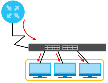
Static Multicast Forwarding By MAC
Use this screen to view and configure static multicast MAC addresses for ports to receive the multicast stream.The following table describes the labels in this screen.
label | description |
|---|---|
Index | This is the index number of the static multicast MAC address rule. |
Active | This field displays whether a static multicast MAC address forwarding rule is active or not. You may temporarily deactivate a rule without deleting it. |
Name | This field displays the descriptive name for identification purposes for a static multicast MAC address-forwarding rule. |
MAC Address | This field displays the multicast MAC address that identifies a multicast group. |
VID | This field displays the ID number of a VLAN group to which frames containing the specified multicast MAC address will be forwarded. |
Port | This field displays the ports within an identified VLAN group to which frames containing the specified multicast MAC address will be forwarded. |
Select an entry’s checkbox to select a specific entry. Otherwise, select the checkbox in the table heading row to select all entries. | |
Add/Edit | Click Add/Edit to add a new rule or edit a selected one. |
Delete | Click Delete to remove the selected rules. |
Add/Edit Static Multicast Forwarding By MAC
Use this screen to add a static multicast MAC address rule for ports to receive the multicast stream.
Click Add/Edit, or select an entry and click Add/Edit in the SWITCHING > Multicast > Static Multicast Forwarding By MAC to display this screen.
The following table describes the labels in this screen.
label | description |
|---|---|
Active | Enable the switch button to activate your rule. You may temporarily deactivate a rule without deleting it by disabling the switch. |
Name | Enter a descriptive name (up to 32 printable ASCII characters except [ ? ], [ | ], [ ' ], [ " ] or [ , ]) for this static multicast MAC address forwarding rule. This is for identification only. |
MAC Address | Enter a multicast MAC address which identifies the multicast group. The last binary bit of the first octet pair in a multicast MAC address must be 1. For example, the first octet pair 00000001 is 01 in hexadecimal, so 01:00:5e:00:00:0A and 01:00:5e:00:00:27 are valid multicast MAC addresses. |
VID | You can forward frames with matching destination multicast MAC address to ports within a VLAN group. Enter the ID that identifies the VLAN group here. If you do NOT have a specific target VLAN, enter 1. |
Port | Enter the ports where frames with destination multicast MAC address that matched the entry above are forwarded. You can enter multiple ports separated by (no space) comma (,) or hyphen (-). For example, enter “3-5” for ports 3, 4, and 5. Enter “3,5,7” for ports 3, 5, and 7. |
Apply | Click Apply to save your changes to the Switch’s run-time memory. The Switch loses these changes if it is turned off or loses power, so use the Save link on the top navigation panel to save your changes to the non-volatile memory when you are done configuring. |
Clear | Click Clear to clear the fields to the factory defaults. |
Cancel | Click Cancel to not save the configuration you make and return to the last screen. |
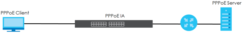
PPPoE Intermediate Agent Overview
A PPPoE Intermediate Agent (PPPoE IA) is deployed between a PPPoE server and PPPoE clients. It helps the PPPoE server identify and authenticate clients by adding subscriber line specific information to PPPoE discovery packets from clients on a per-port or per-port-per-VLAN basis before forwarding them to the PPPoE server.
PPPoE Intermediate Agent Tag Format
If the PPPoE Intermediate Agent is enabled, the Switch adds a vendor-specific tag to PADI (PPPoE Active Discovery Initialization) and PADR (PPPoE Active Discovery Request) packets from PPPoE clients.
This tag is defined in RFC 2516 and has the following format for this feature.
Tag_Type (0x0105) | Tag_Len | Value | i1 | i2 |
The Tag_Type is 0x0105 for vendor-specific tags, as defined in RFC 2516. The Tag_Len indicates the length of Value, i1 and i2. The Value is the 32-bit number 0x00000DE9, which stands for the “ADSL Forum” IANA entry. i1 and i2 are PPPoE intermediate agent sub-options, which contain additional information about the PPPoE client.
Sub-Option Format
There are two types of sub-option: “Agent Circuit ID Sub-option” and “Agent Remote ID Sub-option”. They have the following formats.
SubOpt | Length | Value |
0x01 (1 byte) | N (1 byte) | String (63 bytes) |
SubOpt | Length | Value |
0x02 (1 byte) | N (1 byte) | MAC Address or String (63 bytes) |
The 1 in the first field identifies this as an Agent Circuit ID sub-option and 2 identifies this as an Agent Remote ID sub-option. The next field specifies the length of the field. The Switch takes the Circuit ID string you manually configure for a VLAN on a port as the highest priority and the Circuit ID string for a port as the second priority. In addition, the Switch puts the PPPoE client’s MAC address into the Agent Remote ID Sub-option if you do not specify any user-defined string.
Flexible Circuit ID Syntax with Identifier String and Variables
If you do not configure a Circuit ID string for a VLAN on a specific port or for a specific port, the Switch adds the user-defined identifier string and variables into the Agent Circuit ID Sub-option. The variables can be the slot ID of the PPPoE client, the port number of the PPPoE client and/or the VLAN ID on the PPPoE packet.
The identifier-string, slot ID, port number and VLAN ID are separated from each other by a pound key (#), semi-colon (;), period (.), comma (,), forward slash (/) or space. An Agent Circuit ID Sub-option example is “Switch/07/0123” and indicates the PPPoE packets come from a PPPoE client which is connected to the Switch’s port 7 and belong to VLAN 123.
SubOpt | Length | Value | ||||||
0x01 (1 byte) | N (1 byte) | Identifier String (53 byte) | delimiter (1 byte) | Slot ID (1 byte) | delimiter (1 byte) | Port No (2 byte) | delimiter (1 byte) | VLAN ID (4 bytes) |
WT-101 Default Circuit ID Syntax
If you do not configure a Circuit ID string for a specific VLAN on a port or for a specific port, and disable the flexible Circuit ID syntax in the PPPoE > Intermediate Agent screen, the Switch automatically generates a Circuit ID string according to the default Circuit ID syntax which is defined in the DSL Forum Working Text (WT)-101. The default access node identifier is the host name of the PPPoE intermediate agent and the eth indicates “Ethernet”.
SubOpt | Length | Value | ||||||||
0x01 (1 byte) | N (1 byte) | Access Node Identifier (20 byte) | Space (1 byte) | eth (3 byte) | Space (1 byte) | Slot ID (1 byte) | / (1 byte) | Port No (2 byte) | : (1 byte) | VLAN ID (4 bytes) |
Port State
Every port is either a trusted port or an untrusted port for the PPPoE intermediate agent. This setting is independent of the trusted or untrusted setting for DHCP snooping or ARP inspection. You can also specify the agent sub-options (circuit ID and remote ID) that the Switch adds to PADI and PADR packets from PPPoE clients.
Trusted ports are connected to PPPoE servers.
• If a PADO (PPPoE Active Discovery Offer), PADS (PPPoE Active Discovery Session-confirmation), or PADT (PPPoE Active Discovery Terminate) packet is sent from a PPPoE server and received on a trusted port, the Switch forwards it to all other ports.
• If a PADI or PADR packet is sent from a PPPoE client but received on a trusted port, the Switch forwards it to other trusted ports.
Untrusted ports are connected to subscribers.
• If a PADI, PADR, or PADT packet is sent from a PPPoE client and received on an untrusted port, the Switch adds a vendor-specific tag to the packet and then forwards it to the trusted ports.
• The Switch discards PADO and PADS packets which are sent from a PPPoE server but received on an untrusted port.
PPPoE Intermediate Agent
Use this screen to configure the Switch to give a PPPoE termination server additional subscriber information that the server can use to identify and authenticate a PPPoE client.
The following table describes the labels in this screen.
label | description |
|---|---|
PPPoE Intermediate Agent | |
Active | Enable the switch button to enable the PPPoE intermediate agent globally on the Switch. |
Access-Node-Identifier | Enter up to 20 ASCII printable characters (except [ ? ], [ | ], [ ' ], [ " ], or [ , ]) to identify the PPPoE intermediate agent. Hyphens (-) and spaces are also allowed. The default is the Switch’s host name. |
Circuit-ID Use this section to configure the Circuit ID field in the PADI and PADR packets. The Circuit ID you configure for a specific port (in the SWITCHING > PPPoE Intermediate Agent > PPPoE IA Port screen) or for a specific VLAN on a port (in the SWITCHING > PPPoE Intermediate Agent > PPPoE IA Port VLAN screen) has priority over this. That means, if you also want to configure PPPoE IA Per-Port or Per-Port Per-VLAN setting, leave the fields here empty and configure circuit-id and remote-id in the Per-Port or Per-Port Per-VLAN screen. | |
Active | Enable the switch button to have the Switch add the user-defined identifier string and variables (specified in the Option field) to PADI or PADR packets from PPPoE clients. If you leave this option unselected and do not configure any Circuit ID string (using CLI commands) on the Switch, the Switch will use the string specified in the Access-Node-Identifier field. |
Identifier-String | Specify a string that the Switch adds in the Agent Circuit ID sub-option. You can enter up to 53 printable ASCII characters (except [ ? ], [ | ], [ ' ], [ " ], or [ , ]). Spaces are allowed. |
Option | Select the variables that you want the Switch to generate and add in the Agent Circuit ID sub-option. The variable options include sp, sv, pv and spv which indicate combinations of slot-port, slot-VLAN, port-VLAN and slot-port-VLAN respectively. The Switch enters a zero into the PADI and PADR packets for the slot value. |
Delimiter | Select a delimiter to separate the identifier-string, slot ID, port number and/or VLAN ID from each other. You can use a pound key (#), semi-colon (;), period (.), comma (,), forward slash (/) or space. |
Apply | Click Apply to save your changes to the Switch’s run-time memory. The Switch loses these changes if it is turned off or loses power, so use the Save link on the top navigation panel to save your changes to the non-volatile memory when you are done configuring. |
Cancel | Click Cancel to begin configuring this screen afresh. |
PPPoE IA Port
Use this screen to specify whether individual ports are trusted or untrusted ports and have the Switch add extra information to PPPoE discovery packets from PPPoE clients on a per-port basis.
The following table describes the labels in this screen.
label | description |
|---|---|
Port | This field displays the port number. * means all ports. |
* | Use this row to make the setting the same for all ports. Use this row first and then make adjustments on a port-by-port basis. Changes in this row are copied to all the ports as soon as you make them. |
Server Trusted State | Select whether this port is a trusted port (Trusted) or an untrusted port (Untrusted). Trusted ports are uplink ports connected to PPPoE servers. If a PADO (PPPoE Active Discovery Offer), PADS (PPPoE Active Discovery Session-confirmation), or PADT (PPPoE Active Discovery Terminate) packet is sent from a PPPoE server and received on a trusted port, the Switch forwards it to all other ports. If a PADI or PADR packet is sent from a PPPoE client but received on a trusted port, the Switch forwards it to other trusted ports. Untrusted ports are downlink ports connected to subscribers. If a PADI, PADR, or PADT packet is sent from a PPPoE client and received on an untrusted port, the Switch adds a vendor-specific tag to the packet and then forwards it to the trusted ports. The Switch discards PADO and PADS packets which are sent from a PPPoE server but received on an untrusted port. |
Circuit-ID | Enter a string of up to 63 ASCII characters (except [ ? ], [ | ], [ ' ], [ " ], or [ , ]) that the Switch adds into the Agent Circuit ID sub-option for PPPoE discovery packets received on this port. Spaces are allowed. The Circuit ID you configure for a specific VLAN on a port (in the SWITCHING > PPPoE Intermediate Agent > PPPoE IA Port VLAN screen) has the highest priority. |
Remote-ID | Enter a string of up to 63 ASCII characters (except [ ? ], [ | ], [ ' ], [ " ], or [ , ]) that the Switch adds into the Agent Remote ID sub-option for PPPoE discovery packets received on this port. Spaces are allowed. If you do not specify a string here or in the Remote-ID field for a VLAN on a port, the Switch automatically uses the PPPoE client’s MAC address. The Remote ID you configure for a specific VLAN on a port (in the SWITCHING > PPPoE Intermediate Agent > PPPoE IA Port VLAN screen) has the highest priority. |
Apply | Click Apply to save your changes to the Switch’s run-time memory. The Switch loses these changes if it is turned off or loses power, so use the Save link on the top navigation panel to save your changes to the non-volatile memory when you are done configuring. |
Cancel | Click Cancel to begin configuring this screen afresh. |
PPPoE IA Port VLAN
Use this screen to configure PPPoE IA settings that apply to a specific VLAN on a port.
The following table describes the labels in this screen.
label | description |
|---|---|
Show Port | |
Port | Enter a port number to show the PPPoE Intermediate Agent settings for the specified VLANs on the port. |
Show VLAN Use this section to specify the VLANs you want to configure in the section below. | |
Start VID | Enter the lowest VLAN ID you want to configure in the section below. |
End VID | Enter the highest VLAN ID you want to configure in the section below. |
Apply | Click Apply to display the specified range of VLANs in the section below. |
Port: | This field displays the port number specified above. |
VID | This field displays the VLAN ID of each VLAN in the range specified above. If you configure the * VLAN, the settings are applied to all VLANs. |
* | Use this row to make the setting the same for all VLANs. Use this row first and then make adjustments on a VLAN-by-VLAN basis. Changes in this row are copied to all the VLANs as soon as you make them. |
Circuit-ID | Enter a string of up to 63 ASCII characters (except [ ? ], [ | ], [ ' ], [ " ], or [ , ]) that the Switch adds into the Agent Circuit ID sub-option for this VLAN on the specified port. Spaces are allowed. The Circuit ID you configure here has the highest priority. |
Remote-ID | Enter a string of up to 63 ASCII characters (except [ ? ], [ | ], [ ' ], [ " ], or [ , ]) that the Switch adds into the Agent Remote ID sub-option for this VLAN on the specified port. Spaces are allowed. If you do not specify a string here or in the Remote-ID field for a specific port, the Switch automatically uses the PPPoE client’s MAC address. The Remote ID you configure here has the highest priority. |
Apply | Click Apply to save your changes to the Switch’s run-time memory. The Switch loses these changes if it is turned off or loses power, so use the Save link on the top navigation panel to save your changes to the non-volatile memory when you are done configuring. |
Cancel | Click Cancel to begin configuring this screen afresh. |
PPPoE IA VLAN
Use this screen to set whether the PPPoE Intermediate Agent is enabled on a VLAN and whether the Switch appends the Circuit ID and/or Remote ID to PPPoE discovery packets from a specific VLAN.
The following table describes the labels in this screen.
label | description |
|---|---|
Show VLAN Use this section to specify the VLANs you want to configure in the section below. | |
Start VID | Enter the lowest VLAN ID you want to configure in the section below. |
End VID | Enter the highest VLAN ID you want to configure in the section below. |
Apply | Click Apply to display the specified range of VLANs in the section below. |
VID | This field displays the VLAN ID of each VLAN in the range specified above. If you configure the * VLAN, the settings are applied to all VLANs. |
* | Use this row to make the setting the same for all VLANs. Use this row first and then make adjustments on a VLAN-by-VLAN basis. Changes in this row are copied to all the VLANs as soon as you make them. |
Enabled | Select this option to turn on the PPPoE Intermediate Agent on a VLAN. |
Circuit-ID | Select this option to make the Circuit ID settings for a specific VLAN take effect. |
Remote-ID | Select this option to make the Remote ID settings for a specific VLAN take effect. |
Apply | Click Apply to save your changes to the Switch’s run-time memory. The Switch loses these changes if it is turned off or loses power, so use the Save link on the top navigation panel to save your changes to the non-volatile memory when you are done configuring. |
Cancel | Click Cancel to begin configuring this screen afresh. |
Queuing Method Overview
Queuing is used to help solve performance degradation when there is network congestion. Use the Queuing Method screen to configure queuing algorithms for outgoing traffic. See also Priority Queue Assignment in the SWITCHING > QoS > Priority Queue screen and 802.1p Priority in the PORT > Port Setup screen for related information.
Queuing algorithms allow switches to maintain separate queues for packets from each individual source or flow and prevent a source from monopolizing the bandwidth.
Strictly Priority Queuing
Strictly Priority Queuing (SPQ) services queues based on priority only. As traffic comes into the Switch, traffic on the highest priority queue, Q7 is transmitted first. When that queue empties, traffic on the next highest-priority queue, Q6 is transmitted until Q6 empties, and then traffic is transmitted on Q5 and so on. If higher priority queues never empty, then traffic on lower priority queues never gets sent. SPQ does not automatically adapt to changing network requirements.
Weighted Fair Queuing
Weighted Fair Queuing is used to guarantee each queue's minimum bandwidth based on its bandwidth weight (portion) (the number you configure in the Weight field) when there is traffic congestion. WFQ is activated only when a port has more traffic than it can handle. Queues with larger weights get more guaranteed bandwidth than queues with smaller weights. This queuing mechanism is highly efficient in that it divides any available bandwidth across the different traffic queues. By default, the weight for Q0 is 1, for Q1 is 2, for Q2 is 3, and so on.
Weighted Round Robin Scheduling (WRR)
Round Robin Scheduling services queues on a rotating basis and is activated only when a port has more traffic than it can handle. A queue is given an amount of bandwidth irrespective of the incoming traffic on that port. This queue then moves to the back of the list. The next queue is given an equal amount of bandwidth, and then moves to the end of the list; and so on, depending on the number of queues being used. This works in a looping fashion until a queue is empty.
Weighted Round Robin Scheduling (WRR) uses the same algorithm as round robin scheduling, but services queues based on their priority and queue weight (the number you configure in the queue Weight field) rather than a fixed amount of bandwidth. WRR is activated only when a port has more traffic than it can handle. Queues with larger weights get more service than queues with smaller weights. This queuing mechanism is highly efficient in that it divides any available bandwidth across the different traffic queues and returns to queues that have not yet emptied.
Configure Queuing
Use this screen to set priorities for the queues of the Switch. This distributes bandwidth across the different traffic queues.
The following table describes the labels in this screen.
label | Description |
|---|---|
Port | This label shows the port you are configuring. |
* | Settings in this row apply to all ports. Use this row only if you want to make some settings the same for all ports. Use this row first to set the common settings and then make adjustments on a port-by-port basis. |
Method | Select SPQ (Strictly Priority Queuing), WFQ (Weighted Fair Queuing) or WRR (Weighted Round Robin). Strictly Priority Queuing services queues based on priority only. When the highest priority queue empties, traffic on the next highest-priority queue begins. Q7 has the highest priority and Q0 the lowest. Weighted Fair Queuing is used to guarantee each queue's minimum bandwidth based on their bandwidth portion (weight) (the number you configure in the Weight field). Queues with larger weights get more guaranteed bandwidth than queues with smaller weights. Weighted Round Robin Scheduling services queues on a rotating basis based on their queue weight (the number you configure in the queue Weight field). Queues with larger weights get more service than queues with smaller weights. |
Weight | When you select WFQ or WRR, enter the queue weight here. Bandwidth is divided across the different traffic queues according to their weights. |
Hybrid-SPQ Lowest-Queue | This field is applicable only when you select WFQ or WRR. Select a queue (Q0 to Q7) to have the Switch use SPQ to service the subsequent queues after and including the specified queue for the port. For example, if you select Q5, the Switch services traffic on Q5, Q6 and Q7 using SPQ. Select None to always use WFQ or WRR for the port. |
Apply | Click Apply to save your changes to the Switch’s run-time memory. The Switch loses these changes if it is turned off or loses power, so use the Save link on the top navigation panel to save your changes to the non-volatile memory when you are done configuring. |
Cancel | Click Cancel to begin configuring this screen afresh. |
Priority Queue Overview
IEEE 802.1p defines up to eight separate traffic types by inserting a tag into a MAC-layer frame that contains bits to define class of service. Frames without an explicit priority tag are given the default priority of the ingress port. Use this screen to configure the priority level-to-physical queue mapping. The Switch has eight physical queues that you can map to the eight priority levels.
On the Switch, traffic assigned to higher index queues gets through faster while traffic in lower index queues is dropped if the network is congested.
Priority Queue
Use this screen to assign priority level to each queue.
The following table describes the related labels in this screen.
label | description |
|---|---|
Priority Queue Assignment The following descriptions are based on the traffic types defined in the IEEE 802.1d standard (which incorporates the 802.1p). To map a priority level to a physical queue, select a physical queue from the drop-down menu on the right. | |
Priority 7 | Typically used for network control traffic such as router configuration messages. |
Priority 6 | Typically used for voice traffic that is especially sensitive to jitter (jitter is the variations in delay). |
Priority 5 | Typically used for video that consumes high bandwidth and is sensitive to jitter. |
Priority 4 | Typically used for controlled load, latency-sensitive traffic such as SNA (Systems Network Architecture) transactions. |
Priority 3 | Typically used for “excellent effort” or better than best effort and would include important business traffic that can tolerate some delay. |
Priority 2 | This is for “spare bandwidth”. |
Priority 1 | This is typically used for non-critical “background” traffic such as bulk transfers that are allowed but that should not affect other applications and users. |
Priority 0 | Typically used for best-effort traffic. |
Apply | Click Apply to save your changes to the Switch’s run-time memory. The Switch loses these changes if it is turned off or loses power, so use the Save link on the top navigation panel to save your changes to the non-volatile memory when you are done configuring. |
Cancel | Click Cancel to reset the fields. |
Bandwidth Control Overview
Bandwidth control means defining a maximum allowable bandwidth for incoming and/or out-going traffic flows on a port.
Bandwidth Control
The following table describes the related labels in this screen.
label | description |
|---|---|
Active | Enable the switch button to enable bandwidth control on the Switch. |
Port | This field displays the port number. |
* | Settings in this row apply to all ports. Use this row only if you want to make some settings the same for all ports. Use this row first to set the common settings and then make adjustments on a port-by-port basis. |
Active | Select this checkbox to activate ingress rate limits on this port. |
Ingress Rate | Specify the maximum bandwidth allowed in kilobits per second (Kbps) for the incoming traffic flow on a port. |
Active | Select this checkbox to activate egress rate limits on this port. |
Egress Rate | Specify the maximum bandwidth allowed in kilobits per second (Kbps) for the out-going traffic flow on a port. |
Apply | Click Apply to save your changes to the Switch’s run-time memory. The Switch loses these changes if it is turned off or loses power, so use the Save link on the top navigation panel to save your changes to the non-volatile memory when you are done configuring. |
Cancel | Click Cancel to reset the fields. |