SECURITY
Authentication, Authorization and Accounting (AAA)
The external servers that perform authentication, authorization and accounting functions are known as AAA servers (S). The Switch supports RADIUS (Remote Authentication Dial-In User Service) and TACACS+ (Terminal Access Controller Access-Control System Plus) as the external authentication, authorization, and accounting server on clients (C).
AAA Server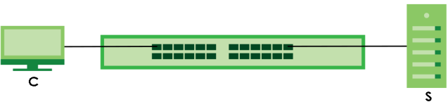
What You Need to Know
Authentication is the process of determining who a user is and validating access to the Switch. The Switch can authenticate users who try to log in based on user accounts configured on the Switch itself. The Switch can also use an external authentication server to authenticate a large number of users.
Authorization is the process of determining what a user is allowed to do. Different user accounts may have higher or lower privilege levels associated with them. For example, user A may have the right to create new login accounts on the Switch but user B cannot. The Switch can authorize users based on user accounts configured on the Switch itself or it can use an external server to authorize a large number of users.
Accounting is the process of recording what a user is doing. The Switch can use an external server to track when users log in, log out, execute commands and so on. Accounting can also record system related actions such as boot up and shut down times of the Switch.
Local User Accounts
By storing user profiles locally on the Switch, your Switch is able to authenticate and authorize users without interacting with a network AAA server. However, there is a limit on the number of users you may authenticate in this way.
RADIUS
RADIUS is a security protocol used to authenticate users by means of an external server instead of (or in addition to) an internal device user database that is limited to the memory capacity of the device. In essence, RADIUS authentication allows you to validate an unlimited number of users from a central location.
RADIUS and TACACS+
RADIUS and TACACS+ are security protocols used to authenticate users by means of an external server instead of (or in addition to) an internal device user database that is limited to the memory capacity of the device. In essence, RADIUS and TACACS+ authentication both allow you to validate an unlimited number of users from a central location.
The following table describes some key differences between RADIUS and TACACS+.
RADIUS | TACACS+ | |
|---|---|---|
Transport Protocol | UDP (User Datagram Protocol) | TCP (Transmission Control Protocol) |
Encryption | Encrypts the password sent for authentication. | All communication between the client (the Switch) and the TACACS server is encrypted. |
RADIUS Server Setup
Use this screen to configure your RADIUS server settings.
The following table describes the labels in this screen.
label | description |
|---|---|
Authentication Server Use this section to configure your RADIUS authentication settings. | |
Mode | This field is only valid if you configure multiple RADIUS servers. Select index-priority and the Switch tries to authenticate with the first configured RADIUS server, if the RADIUS server does not respond then the Switch tries to authenticate with the second RADIUS server. Select round-robin to alternate between the RADIUS servers that it sends authentication requests to. |
Timeout | Specify the amount of time in seconds that the Switch waits for an authentication request response from the RADIUS server. If you are using two RADIUS servers then the timeout value is divided between the two RADIUS servers. For example, if you set the timeout value to 30 seconds, then the Switch waits for a response from the first RADIUS server for 15 seconds and then tries the second RADIUS server. |
Delete | Check this box if you want to remove an existing RADIUS server entry from the Switch. This entry is deleted when you click Apply. |
Index | This is a read-only number representing a RADIUS server entry. |
IP Address | Enter the IPv4 address or IPv6 address of an external RADIUS server. |
UDP Port | The default port of a RADIUS server for authentication is 1812. You need not change this value unless your network administrator instructs you to do so. |
Shared Secret | Specify a password (up to 32 alphanumeric characters except [ ? ], [ | ], [ ' ], [ " ], [ space ], or [ , ]) as the key to be shared between the external RADIUS server and the Switch. This key is not sent over the network. This key must be the same on the external RADIUS server and the Switch. |
Encrypted Shared Secret | This displays the encrypted shared secret in ‘*’ format if you enabled Server Key Encryption in SECURITY > AAA > AAA Setup > AAA Setup. |
Accounting Server Use this section to configure your RADIUS accounting server settings. | |
Timeout | Specify the amount of time in seconds that the Switch waits for an accounting request response from the RADIUS accounting server. |
Delete | Check this box if you want to remove an existing RADIUS accounting server entry from the Switch. This entry is deleted when you click Apply. |
Index | This is a read-only number representing a RADIUS accounting server entry. |
IP Address | Enter the IPv4 address or IPv6 address of an external RADIUS accounting server. |
UDP Port | The default port of a RADIUS accounting server for accounting is 1813. You need not change this value unless your network administrator instructs you to do so. |
Shared Secret | Specify a password (up to 32 alphanumeric characters except [ ? ], [ | ], [ ' ], [ " ], [ space ], or [ , ]) as the key to be shared between the external RADIUS accounting server and the Switch. This key is not sent over the network. This key must be the same on the external RADIUS accounting server and the Switch. |
Encrypted Shared Secret | This displays the encrypted shared secret in ‘*’ format if you enabled Server Key Encryption in SECURITY > AAA > AAA Setup > AAA Setup. |
Attribute Use this section to define the RADIUS server attribute for its account. | |
NAS-IP-Address | Enter the IP address of the NAS (Network Access Server). |
Apply | Click Apply to save your changes to the Switch’s run-time memory. The Switch loses these changes if it is turned off or loses power, so use the Save link on the top navigation panel to save your changes to the non-volatile memory when you are done configuring. |
Cancel | Click Cancel to begin configuring this screen afresh. |
TACACS+ Server Setup
Use this screen to configure your TACACS+ server settings.
The following table describes the labels in this screen.
label | description |
|---|---|
Authentication Server Use this section to configure your TACACS+ authentication settings. | |
Mode | This field is only valid if you configure multiple TACACS+ servers. Select index-priority and the Switch tries to authenticate with the first configured TACACS+ server, if the TACACS+ server does not respond then the Switch tries to authenticate with the second TACACS+ server. Select round-robin to alternate between the TACACS+ servers that it sends authentication requests to. |
Timeout | Specify the amount of time in seconds that the Switch waits for an authentication request response from the TACACS+ server. If you are using index-priority for your authentication and you are using two TACACS+ servers then the timeout value is divided between the two TACACS+ servers. For example, if you set the timeout value to 30 seconds, then the Switch waits for a response from the first TACACS+ server for 15 seconds and then tries the second TACACS+ server. |
Delete | Check this box if you want to remove an existing TACACS+ server entry from the Switch. This entry is deleted when you click Apply. |
Index | This is a read-only number representing a TACACS+ server entry. |
IP Address | Enter the IP address of an external TACACS+ server in dotted decimal notation. |
TCP Port | The default port of a TACACS+ server for authentication is 49. You need not change this value unless your network administrator instructs you to do so. |
Shared Secret | Specify a password (up to 32 alphanumeric characters except [ ? ], [ | ], [ ' ], [ " ], [ space ], or [ , ]) as the key to be shared between the external TACACS+ server and the Switch. This key is not sent over the network. This key must be the same on the external TACACS+ server and the Switch. |
Encrypted Shared Secret | This displays the encrypted shared secret in ‘*’ format if you enabled Server Key Encryption in SECURITY > AAA > AAA Setup > AAA Setup. |
Accounting Server Use this section to configure your TACACS+ accounting settings. | |
Timeout | Specify the amount of time in seconds that the Switch waits for an accounting request response from the TACACS+ server. |
Delete | Check this box if you want to remove an existing TACACS+ accounting server entry from the Switch. This entry is deleted when you click Apply. |
Index | This is a read-only number representing a TACACS+ accounting server entry. |
IP Address | Enter the IP address of an external TACACS+ accounting server in dotted decimal notation. |
TCP Port | The default port of a TACACS+ accounting server is 49. You need not change this value unless your network administrator instructs you to do so. |
Shared Secret | Specify a password (up to 32 alphanumeric characters except [ ? ], [ | ], [ ' ], [ " ], [ space ], or [ , ]) as the key to be shared between the external TACACS+ accounting server and the Switch. This key is not sent over the network. This key must be the same on the external TACACS+ accounting server and the Switch. |
Encrypted Shared Secret | This displays the encrypted shared secret in ‘*’ format if you enabled Server Key Encryption in SECURITY > AAA > AAA Setup > AAA Setup. |
Apply | Click Apply to save your changes to the Switch’s run-time memory. The Switch loses these changes if it is turned off or loses power, so use the Save link on the top navigation panel to save your changes to the non-volatile memory when you are done configuring. |
Cancel | Click Cancel to begin configuring this screen afresh. |
AAA Setup
Use this screen to configure authentication, authorization and accounting settings on the Switch.
The following table describes the labels in this screen.
label | description |
|---|---|
Server Key Encryption Use this section to configure server key encryption settings. | |
Active | Enable the switch button to enable server key (shared secret) encryption for RADIUS server and TACACS+ server for security enhancement. The shared secret will be stored on the Switch in an encrypted format and displayed as ‘*’ in the SECURITY > AAA > RADIUS Server Setup > RADIUS Server Setup and SECURITY > AAA > TACACS+ Server Setup > TACACS+ Server Setup screens. |
Authentication Use this section to specify the methods used to authenticate users accessing the Switch. | |
Privilege Enable | These fields specify which database the Switch should use (first, second and third) to authenticate access privilege level for administrator accounts (users for Switch management). Configure the access privilege of accounts through commands for local authentication. The TACACS+ and RADIUS are external servers. Before you specify the priority, make sure you have set up the corresponding database correctly first. You can specify up to three methods for the Switch to authenticate the access privilege level of administrators. The Switch checks the methods in the order you configure them (first Method 1, then Method 2 and finally Method 3). You must configure the settings in the Method 1 field. If you want the Switch to check other sources for access privilege level specify them in Method 2 and Method 3 fields. Select local to have the Switch check the access privilege configured for local authentication. Select radius or tacacs+ to have the Switch check the access privilege through the external servers. |
Login | These fields specify which database the Switch should use (first, second and third) to authenticate administrator accounts (users for Switch management). Configure the local user accounts in the SYSTEM > Logins > Logins screen. The TACACS+ and RADIUS are external servers. Before you specify the priority, make sure you have set up the corresponding database correctly first. You can specify up to three methods for the Switch to authenticate administrator accounts. The Switch checks the methods in the order you configure them (first Method 1, then Method 2 and finally Method 3). You must configure the settings in the Method 1 field. If you want the Switch to check other sources for administrator accounts, specify them in Method 2 and Method 3 fields. Select local to have the Switch check the administrator accounts configured in the SYSTEM > Logins > Logins screen. Select radius to have the Switch check the administrator accounts configured through the RADIUS Server. Select tacacs+ to have the Switch check the administrator accounts configured through the TACACS+ Server. |
Authorization Use this section to configure authorization settings on the Switch. | |
Type | Set whether the Switch provides the following services to a user. • Exec: Allow an administrator which logs into the Switch through Telnet or SSH to have a different access privilege level assigned through the external server. • Dot1x: Allow an IEEE 802.1x client to have different bandwidth limit or VLAN ID assigned through the external server. |
Active | Enable the switch button to activate authorization for a specified event type. |
Console | Select this to allow an administrator which logs in the Switch through the console port to have different access privilege level assigned through the external server. |
Method | Select whether you want to use radius or tacacs+ for authorization of specific types of events. RADIUS is the only method for IEEE 802.1x authorization. |
Accounting Use this section to configure accounting settings on the Switch. | |
Update Period | This is the amount of time in minutes before the Switch sends an update to the accounting server. This is only valid if you select the start-stop option for the Exec or Dot1x entries. |
Type | The Switch supports the following types of events to be sent to the accounting servers: • System – Configure the Switch to send information when the following system events occur: system boots up, system shuts down, system accounting is enabled, system accounting is disabled. • Exec – Configure the Switch to send information when an administrator logs in and logs out through the console port, telnet or SSH. • Dot1x – Configure the Switch to send information when an IEEE 802.1x client begins a session (authenticates through the Switch), ends a session as well as interim updates of a session. • Commands – Configure the Switch to send information when commands of specified privilege level and higher are executed on the Switch. |
Active | Enable the switch button to activate accounting for a specified event type. |
Broadcast | Select this to have the Switch send accounting information to all configured accounting servers at the same time. If you do not select this and you have two accounting servers set up, then the Switch sends information to the first accounting server and if it does not get a response from the accounting server then it tries the second accounting server. |
Mode | The Switch supports two modes of recording login events. Select: • start-stop – to have the Switch send information to the accounting server when a user begins a session, during a user’s session (if it lasts past the Update Period), and when a user ends a session. • stop-only – to have the Switch send information to the accounting server only when a user ends a session. |
Method | Select whether you want to use radius or tacacs+ for accounting of specific types of events. tacacs+ is the only method for recording Commands type of event. |
Privilege | This field is only configurable for Commands type of event. Select the threshold command privilege level for which the Switch should send accounting information. The Switch will send accounting information when commands at the level you specify and higher are executed on the Switch. |
Apply | Click Apply to save your changes to the Switch’s run-time memory. The Switch loses these changes if it is turned off or loses power, so use the Save link on the top navigation panel to save your changes to the non-volatile memory when you are done configuring. |
Cancel | Click Cancel to begin configuring this screen afresh. |
Access Control Overview
FTP is allowed one session each, Telnet and SSH share nine sessions, up to five web sessions (five different user names and passwords) and/or limitless SNMP access control sessions are allowed.
SSH | Telnet | FTP | Web | SNMP |
Share up to nine sessions | One session | Up to five accounts | No limit | |
Telnet access control session cannot coexist when multi-login is disabled.
Service Access Control
Service Access Control allows you to decide what services you may use to access the Switch. You may also change the default service port and configure “trusted computers” for each service in the SECURITY > Access Control > Remote Management > Remote Management screen.
The following table describes the fields in this screen.
LABEL | Description |
|---|---|
Services | Services you may use to access the Switch are listed here. Telnet and SSH give access to a limited version of the Command Line Interface (CLI) to display information. |
Active | Enable the switch button for the corresponding services that you want to allow to access the Switch. |
Service Port | For Telnet, SSH, FTP, HTTP or HTTPS services, you may change the default service port by typing the new port number in the Service Port field. If you change the default port number then you will have to let people (who wish to use the service) know the new port number for that service. |
Timeout | Enter how many minutes (from 1 to 255) a management session can be left idle before the session times out. After it times out you have to log in with your password again. Very long idle timeouts may have security risks. |
Login Timeout | The Telnet or SSH server do not allow multiple user logins at the same time. Enter how many seconds (from 30 to 300 seconds) a login session times out. After it times out you have to start the login session again. Very long login session timeouts may have security risks. For example, if User A attempts to connect to the Switch (through SSH), but during the login stage, do not enter the user name and/or password, User B cannot connect to the Switch (through SSH) before the Login Timeout for User A expires (default 150 seconds). |
Redirect to HTTPS | This option allows your web browser to automatically redirect to a secure page, from HTTP to HTTPS (secure hypertext transfer protocol). SSL (Secure Sockets Layer) in HTTPS encrypts the transferred data by changing plain text to random letters and numbers. |
Apply | Click Apply to save your changes to the Switch’s run-time memory. The Switch loses these changes if it is turned off or loses power, so use the Save link on the top navigation panel to save your changes to the non-volatile memory when you are done configuring. |
Cancel | Click Cancel to begin configuring this screen afresh. |
Remote Management
Use this screen to specify a group of one or more “trusted computers” from which an administrator may use a service to manage the Switch.
The following table describes the labels in this screen.
label | Description |
|---|---|
Entry | This is the client set index number. A “client set” is a group of one or more “trusted computers” from which an administrator may use a service to manage the Switch. |
Active | Enable the switch button to activate this secured client set. Clear the checkbox if you wish to temporarily disable the set without deleting it. |
Start Address End Address | Configure the IPv4 address range of trusted computers from which you can manage this Switch. The Switch checks if the client IPv4 address of a computer requesting a service or protocol matches the range set here. The Switch immediately disconnects the session if it does not match. |
Telnet / FTP / HTTP / ICMP / SNMP / SSH / HTTPS | Select services that may be used for managing the Switch from the specified trusted computers. |
Apply | Click Apply to save your changes to the Switch’s run-time memory. The Switch loses these changes if it is turned off or loses power, so use the Save link on the top navigation panel to save your changes to the non-volatile memory when you are done configuring. |
Cancel | Click Cancel to begin configuring this screen afresh. |
Remote Management (IPv6)
Use this screen to specify a group of one or more “trusted computers using IPv6 addresses” from which an administrator may use a service to manage the Switch.
The following table describes the labels in this screen.
label | Description |
|---|---|
Entry | This is the client set index number. A “client set” is a group of one or more “trusted computers” from which an administrator may use a service to manage the Switch. |
Active | Enable the switch button to activate this secured client set. Clear the checkbox if you wish to temporarily disable the set without deleting it. |
Start Address End Address | Configure the IPv6 address range of trusted computers from which you can manage this Switch. The Switch checks if the client IPv6 address of a computer requesting a service or protocol matches the range set here. The Switch immediately disconnects the session if it does not match. |
Telnet / FTP / HTTP / ICMP / SNMP / SSH / HTTPS | Select services that may be used for managing the Switch from the specified trusted computers. |
Apply | Click Apply to save your changes to the Switch’s run-time memory. The Switch loses these changes if it is turned off or loses power, so use the Save link on the top navigation panel to save your changes to the non-volatile memory when you are done configuring. |
Cancel | Click Cancel to begin configuring this screen afresh. |
Account Security
Use this screen to encrypt all passwords configured in the Switch. This setting will affect how the password is shown (as plain text or encrypted text) in the configuration file saved in MAINTENANCE > Configuration > Save Configuration > Save Configuration.
Password Encryption encrypts all passwords in the configuration file. However, if you want to show some passwords as plain text in the configuration file, select them as below:
• Authentication information configured for Authentication in the SECURITY > AAA > AAA Setup > AAA Setup screen (Method 1/2/3 setting in the Privilege Enable and Login fields).
• Authorization information configured for Authorization in the SECURITY > AAA > AAA Setup > AAA Setup screen (Active/Console/Method setting in the Exec and Dot1x fields).
• System account information configured in the Switch (admin, user login name, and password).
• SNMP user account information configured in the SYSTEM > SNMP > SNMP User screen (password for SNMP user authentication in the Authentication field, and the password for the encryption method for SNMP communication in the Privacy field).
The following table describes the labels in this screen.
label | Description |
|---|---|
Account Security | |
Password Encryption | Click the switch to the right to encrypt all passwords configured on the Switch (default is enabled). This displays the password as encrypted text, in a saved configuration file. Otherwise, the passwords configured on the Switch are displayed in plain text. |
Password Complexity | Click the switch to the right to enforce a strong login password (default is disabled). The password rules are: • 9 to 32 characters in length • Include at least three of these: numbers, uppercase letters, lowercase letters, and special characters (for example, ‘Ea5yPas5W0rd’) • Cannot match your login username • Cannot use the same character (case insensitive) or number three or more times in a row (for example, ‘777’, ‘AaA’) • Cannot use four or more sequential keyboard characters (case insensitive) or numbers (for example, ‘qWer’, ‘1234’), and • Cannot use the present password again. Alternatively, click the switch to the left. The password rules is: • 4 to 32 characters in length |
Apply | Click Apply to save your changes for Account Security to the Switch’s run-time memory. The Switch loses these changes if it is turned off or loses power, so use the Save link on the top navigation panel to save your changes to the non-volatile memory when you are done configuring. |
Cancel | Click Cancel to begin configuring Account Security afresh. |
Display | |
AAA | Select which specific information to display in plain text, in the saved configuration file. • Authentication • Authorization • Server |
User | Select which user account information to display in plain text, in the saved configuration file. • System • SNMP |
Apply | Click Apply to save your changes for Display to the Switch’s run-time memory. The Switch loses these changes if it is turned off or loses power, so use the Save link on the top navigation panel to save your changes to the non-volatile memory when you are done configuring. |
Cancel | Click Cancel to begin configuring Display afresh. |
Lock the IP Address
Use this screen to allow the Switch to block login requests after multiple failed attempts occur within a specific time frame.
The following table describes the labels in this screen.
label | Description |
|---|---|
Active | Click the switch to the right to allow the Switch to detect and block multiple failed login attempts from the same IP address (default is disable). |
Block Period | Enter how many minutes (from 1 to 65535) the IP address that exceeded the Retry Count will be stopped from trying to log in again (default is 5 minutes). |
Retry Count | Enter how many login attempts (from 1 to 99) to allow an IP address (default is 5 attempts). |
Attempt Timeout | Enter how many minutes (from 1 to 65535) if the login attempts exceed the Retry Count, to stop the IP address from trying to log in again (default is 5 minutes). For example, the Switch will block all logins from the same IP address (IP ‘A’) for 5 minutes if there are 6 failed attempts within 10 minutes. IP ‘A’ cannot try to log in to the Switch until the Block Period expires. |
Apply | Click Apply to save your changes to the Switch’s run-time memory. The Switch loses these changes if it is turned off or loses power, so use the Save link on the top navigation panel to save your changes to the non-volatile memory when you are done configuring. |
Cancel | Click Cancel to begin configuring this screen afresh. |
Classifier Overview
This chapter introduces and shows you how to configure the packet classifier on the Switch. It also discusses Quality of Service (QoS) and classifier concepts as employed by the Switch.
Quality of Service (QoS) refers to both a network's ability to deliver data with minimum delay, and the networking methods used to control the use of bandwidth. Without QoS, all traffic data is equally likely to be dropped when the network is congested. This can cause a reduction in network performance and make the network inadequate for time-critical application such as video-on-demand.
A classifier groups traffic into data flows according to specific criteria such as the source address, destination address, source port number, destination port number or incoming port number. For example, you can configure a classifier to select traffic from the same protocol port (such as Telnet) to form a flow.
Classifier Status
Use this screen to view the classifiers configured on the Switch and how many times the traffic matches the rules.
The following table describes the labels in this screen.
label | description |
|---|---|
Index | This field displays the index number of the rule. |
Active | This field displays whether the rule is activated or not. |
Weight | This field displays the rule’s weight. This is to indicate a rule’s priority when the match order is set to manual in the SECURITY > ACL > Classifier > Classifier Global Setting screen. The higher the number, the higher the rule’s priority. |
Name | This field displays the descriptive name for this rule. This is for identification purpose only. |
Match Count | This field displays the number of times a rule is applied. It displays '–' if the rule does not have count enabled. |
Rule | This field displays a summary of the classifier rule’s settings. |
Clear the Classifier | |
Any | Select Any, then click Clear to clear the matched count for all classifiers. |
Classifier | Select Classifier, enter a classifier rule name and then click Clear to erase the recorded statistical information for that classifier, or select Any to clear statistics for all classifiers. |
Clear | Click Clear to erase the recorded statistical information for the classifier. |
Classifier Setup
Use this screen to view and configure the classifiers. After you define the classifier, you can specify actions (or policy) to act upon the traffic that matches the rules.
The following table describes the labels in this screen.
label | Description |
|---|---|
Index | This field displays the index number of the rule. |
Active | This field displays Yes when the rule is activated and No when it is deactivated. |
Weight | The field displays the priority of the rule when the match order is in manual mode. A higher weight means a higher priority. |
Name | This field displays the descriptive name for this rule. This is for identification purpose only. |
Rule | This field displays a summary of the classifier rule’s settings. |
Select an entry’s checkbox to select a specific entry. Otherwise, select the checkbox in the table heading row to select all entries. | |
Add/Edit | Click Add/Edit to add a new entry or edit a selected one. |
Delete | Click Delete to remove the selected entries. |
Add/Edit a Classifier
Use this screen to define the classifiers. After you define the classifier, you can specify actions (or policy) to act upon the traffic that matches the rules.
Click Add/Edit, or select an entry and click Add/Edit in the SECURITY > ACL > Classifier > Classifier Setup screen to display this screen.
The following table describes the labels in this screen.
label | Description |
|---|---|
Active | Enable the switch button to enable this rule. |
Name | Enter a descriptive name for this rule for identifying purposes. You can enter up to 32 printable ASCII characters except [ ? ], [ | ], [ ' ], [ " ], or [ , ]. |
Weight | Enter a number between 0 and 65535 to specify the rule’s weight. When the match order is in manual mode in the Classifier Global Setting screen, a higher weight means a higher priority. |
Log | Select this option to have the Switch create a log message when the rule is applied and record the number of matched packets in a particular time interval. |
Count | Select this option to have the Switch count how many times the rule is applied. |
Time Range | Select the name of the pre-configured schedule that you want to apply to the rule. The rule will be active only at the scheduled date and/or time. If you select None, the rule will be active all the time. |
Ingress Port | |
Port | Select Any to apply the rule to all ports. Alternatively, to specify the ports enter the port numbers to which the rule should be applied. You can enter multiple ports separated by (no space) comma (,) or hyphen (-). For example, enter “3-5” for ports 3, 4, and 5. Enter “3,5,7” for ports 3, 5, and 7. |
Trunk | Select Any to apply the rule to all trunk groups. Alternatively, to specify multiple trunks, enter the trunk group ID to apply the rule to multiple trunks. You can enter multiple trunks with (t) or (T) then the trunk group ID separated by (no space) comma (,) or hyphen (-). For example, enter “t3-t5” for trunks 3, 4, and 5. Enter “T3,T5,T7” for trunks 3, 5, and 7. |
Layer 2 Specify the fields below to configure a layer 2 classifier. | |
VLAN | Select Any to classify traffic from any VLAN or select the second option and specify the source VLAN ID in the field provided. |
Priority | Select Any to classify traffic from any priority level or select the second option and specify a priority level in the field provided. |
Ethernet Type | Select an Ethernet type or select Other and enter the Ethernet type number in hexadecimal value. |
Source MAC Address | Select Any to apply the rule to all MAC addresses. To specify a source, select MAC/Mask to enter the source MAC address of the packet in valid MAC address format (six hexadecimal character pairs) and type the mask for the specified MAC address to determine which bits a packet’s MAC address should match. Enter “f” for each bit of the specified MAC address that the traffic’s MAC address should match. Enter “0” for the bits of the matched traffic’s MAC address, which can be of any hexadecimal characters. For example, if you set the MAC address to 00:13:49:00:00:00 and the mask to ff:ff:ff:00:00:00, a packet with a MAC address of 00:13:49:12:34:56 matches this criteria. If you leave the Mask field blank, the Switch automatically sets the mask to ff:ff:ff:ff:ff:ff. |
Destination MAC Address | Select Any to apply the rule to all MAC addresses. To specify a destination, select MAC/Mask to enter the destination MAC address of the packet in valid MAC address format (six hexadecimal character pairs) and type the mask for the specified MAC address to determine which bits a packet’s MAC address should match. Enter “f” for each bit of the specified MAC address that the traffic’s MAC address should match. Enter “0” for the bits of the matched traffic’s MAC address, which can be of any hexadecimal characters. For example, if you set the MAC address to 00:13:49:00:00:00 and the mask to ff:ff:ff:00:00:00, a packet with a MAC address of 00:13:49:12:34:56 matches this criteria. If you leave the Mask field blank, the Switch automatically sets the mask to ff:ff:ff:ff:ff:ff. |
Layer 3 Specify the fields below to configure a layer 3 classifier. | |
IPv4/IPv6 DSCP | Select Any to classify traffic from any DSCP or select the second option and specify a DSCP (DiffServ Code Point) number between 0 and 63 in the field provided. |
Precedence | Select Any to classify traffic from any precedence or select the second option and specify an IP Precedence (the first 3 bits of the 8-bit ToS field) value between 0 and 7 in the field provided. |
ToS | Select Any to classify traffic from any ToS or select the second option and specify Type of Service (the last 5 bits of the 8-bit ToS field) value between 0 and 255 in the field provided. |
IP Protocol | Select an IPv4 protocol type or select Other and enter the protocol number in decimal value. You may select Establish Only for TCP protocol type. This means that the Switch will pick out the packets that are sent to establish TCP connections. |
IPv6 Next Header | Select an IPv6 protocol type or select Other and enter an 8-bit next header in the IPv6 packet. The Next Header field is similar to the IPv4 Protocol field. The IPv6 protocol number ranges from 1 to 255. You may select Establish Only for TCP protocol type. This means that the Switch will identify packets that initiate or acknowledge (establish) TCP connections. |
Source IP Address/Prefix | Enter a source IP address in dotted decimal notation. Specify the address prefix by entering the number of ones in the subnet mask. A subnet mask can be represented in a 32-bit notation. For example, the subnet mask “255.255.255.0” can be represented as “11111111.11111111.11111111.00000000”, and counting up the number of ones in this case results in 24. |
Destination IP Address/Prefix | Enter a destination IP address in dotted decimal notation. Specify the address prefix by entering the number of ones in the subnet mask. |
Layer 4 Specify the fields below to configure a layer 4 classifier. | |
Source Socket Number | Select Any to apply the rule to all TCP/UDP protocol port numbers or select the second option and enter a TCP/UDP protocol port number. |
Destination Socket Number | Select Any to apply the rule to all TCP/UDP protocol port numbers or select the second option and enter a TCP/UDP protocol port number. |
Apply | Click Apply to save your changes to the Switch’s run-time memory. The Switch loses these changes if it is turned off or loses power, so use the Save link on the top navigation panel to save your changes to the non-volatile memory when you are done configuring. |
Clear | Click Clear to clear the fields to the factory defaults. |
Cancel | Click Cancel to not save the configuration you make and return to the last screen. |
Classifier Global Setting
Use this screen to configure the match order and enable logging on the Switch.
The following table describes the labels in this screen.
label | Description |
|---|---|
Match Order | Use this field to set the match order for the classifier rules. A traffic flow can only be classified to one classifier. When a traffic flow matches more than one classifier rule, the Switch classifies the traffic based on the Match Order. Select manual to have classifier rules applied according to the weight of each rule you configured in SECURITY > ACL > Classifier > Classifier Setup. If they have the same weight, the Switch will classify the traffic to the classifier with a higher name priority (see Classifier Name Priority). Alternatively, select auto to have classifier rules applied according to the layer of the item configured in the rule. Layer-4 items have the highest priority, and layer-2 items has the lowest priority. For example, you configure a layer-2 item (VLAN ID) in classifier A and configure a layer-3 item (source IP address) in classifier B. When an incoming packet matches both classifier rules, classifier B has priority over classifier A. If both classifiers have the same priority, the Switch will apply the classifier with a higher name priority. Classifier Name Priority The longer the classifier name, the higher the classifier priority. If two classifier names are the same length, the bigger the character, the higher the classifier priority. The lowercase letters (such as a and b) have higher priority than the capitals (such as A and B) in the classifier name. For example, the classifier with the name of class 2, class a or class B takes priority over the classifier with the name of class 1 or class A. |
Logging | |
Active | Enable the switch button to allow the Switch to create a log when packets match a classifier rule during a defined time interval. |
Interval | Set the length of the time period (in seconds) to count matched packets for a classifier rule. Enter an integer from 0 – 65535. 0 means that no logging is done. |
Apply | Click Apply to save your changes to the Switch’s run-time memory. The Switch loses these changes if it is turned off or loses power, so use the Save link on the top navigation panel to save your changes to the non-volatile memory when you are done configuring. |
Cancel | Click Cancel to begin configuring this screen afresh. |
Policy Rule
A classifier distinguishes traffic into flows based on the configured criteria. A policy rule ensures that a traffic flow gets the requested treatment in the network.
Policy Rules
The following table describes the labels in this screen.
label | Description |
|---|---|
Index | This field displays the policy index number. |
Active | This field displays whether policy is activated or not. |
Name | This field displays the name you have assigned to this policy. |
Classifier(s) | This field displays the names of the classifier to which this policy applies. |
Select an entry’s checkbox to select a specific entry. Otherwise, select the checkbox in the table heading row to select all entries. | |
Add/Edit | Click Add/Edit to add a new entry or edit a selected one. |
Delete | Click Delete to remove the selected entries. |
Add/Edit a Policy Rule
You must first configure a classifier in the SECURITY > ACL > Classifier > Classifier Setup screen.
Click Add/Edit, or select an entry and click Add/Edit in the SECURITY > ACL > Policy Rule > Policy Rule screen to display this screen.
The following table describes the labels in this screen.
label | Description |
|---|---|
Source & Destination | |
Active | Enable the switch button to enable the policy. |
Name | Enter a descriptive name for identification purposes. You can enter up to 32 printable ASCII characters except [ ? ], [ | ], [ ' ], [ " ], or [ , ]. |
Classifier(s) | This field displays the active classifiers you configure in the SECURITY > ACL > Classifier > Classifier Setup screen. Select the classifiers to which this policy rule applies. To select more than one classifier, press [SHIFT] and select the choices at the same time. |
General Parameters Set the fields below for this policy. You only have to set the fields that is related to the actions you configure in the Action field. | |
Vlan ID | Specify a VLAN ID. |
Egress Port | Enter the number of an outgoing port. |
Priority | Specify a priority level. |
TOS | Specify the Type Of Service (TOS) priority level. |
Rate Limit Parameters You can configure the desired bandwidth available to a traffic flow. Traffic that exceeds the maximum bandwidth allocated (in cases where the network is congested) is called out-of-profile traffic. | |
Bandwidth | Specify the bandwidth in kilobit per second (Kbps). Enter a number between 1 and 1000000. |
Action Specify the actions the Switch takes on the associated classified traffic flow. Say you have a traffic flow that matches several classifiers, and you specify a different policy rule for each. The Switch only classifies the traffic flow to the classifier with the highest Match Order. The Switch then applies the policy rule with which the classifier is associated. You can set the classifier Match Order rule (manual or auto) in the ACL > Classfier > Classifier Global settings screen (see Classifier Global Setting for more information). Let’s say you set two classifiers (Class 1 and Class 2) and both identify all traffic from MAC address 11:22:33:44:55:66 on port 3. If Policy 1 applies to Class 1 and the action is to drop the packets, Policy 2 applies to Class 2 and the action is to forward the packets to the egress port, the Switch will forward the packets. If Policy 1 applies to Class 1 and the action is to drop the packets, Policy 2 applies to Class 2 and the action is to enable bandwidth limitation, the Switch will discard the packets immediately. If Policy 1 applies to Class 1 and the action is to forward the packets to the egress port, Policy 2 applies to Class 2 and the action is to enable bandwidth limitation, the Switch will forward the packets. | |
Forwarding | Select No change to forward the packets. Select Discard the packet to drop the packets. |
Priority | Select No change to keep the priority setting of the frames. Select Set the packet’s 802.1p priority to replace the packet’s 802.1p priority field with the value you set in the Priority field and put the packets in the designated queue. |
Outgoing | Select Send the packet to the mirror port to send the packet to the mirror port. Select Send the packet to the egress port to send the packet to the egress port. Select Set the packet's VLAN ID to set the packet’s VLAN ID. |
Rate Limit | Select Enable to activate bandwidth limitation on the traffic flows then set the actions to be taken on out-of-profile packets. |
Apply | Click Apply to save your changes to the Switch’s run-time memory. The Switch loses these changes if it is turned off or loses power, so use the Save link on the top navigation panel to save your changes to the non-volatile memory when you are done configuring. |
Clear | Click Clear to clear the fields to the factory defaults. |
Cancel | Click Cancel to not save the configuration you make and return to the last screen. |
Storm Control Overview
Storm control limits the number of broadcast, multicast and destination lookup failure (DLF) packets the Switch receives per second on the ports. When the maximum number of allowable broadcast, multicast and/or DLF packets is reached per second, the subsequent packets are discarded. Enable this feature to reduce broadcast, multicast and/or DLF packets in your network. You can specify limits for each packet type on each port.
Storm Control Setup
The following table describes the labels in this screen.
label | description |
|---|---|
Active | Enable the switch button to enable traffic storm control on the Switch. Disable the switch button to disable this feature. |
Port | This field displays the port number. |
* | Settings in this row apply to all ports. Use this row only if you want to make some settings the same for all ports. Use this row first to set the common settings and then make adjustments on a port-by-port basis. |
Broadcast (pkt/s) | Select this option and specify how many broadcast packets the port receives per second. |
Multicast (pkt/s) | Select this option and specify how many multicast packets the port receives per second. |
DLF (pkt/s) | Select this option and specify how many destination lookup failure (DLF) packets the port receives per second. |
Apply | Click Apply to save your changes to the Switch’s run-time memory. The Switch loses these changes if it is turned off or loses power, so use the Save link on the top navigation panel to save your changes to the non-volatile memory when you are done configuring. |
Cancel | Click Cancel to reset the fields. |
Error-Disable Overview
CPU Protection Overview
Switches exchange protocol control packets in a network to get the latest networking information. If a switch receives large numbers of control packets, such as ARP, BPDU or IGMP packets, which are to be processed by the CPU, the CPU may become overloaded and be unable to handle regular tasks properly.
The CPU protection feature allows you to limit the rate of ARP, BPDU and IGMP packets to be delivered to the CPU on a port. This enhances the CPU efficiency and protects against potential DoS attacks or errors from other networks. You then can choose to drop control packets that exceed the specified rate limit or disable a port on which the packets are received.
Error-Disable Recovery Overview
Some features, such as loop guard or CPU protection, allow the Switch to shut down a port or discard specific packets on a port when an error is detected on the port. For example, if the Switch detects that packets sent out the ports loop back to the Switch, the Switch can shut down the ports automatically. After that, you need to enable the ports or allow the packets on a port manually through the Web Configurator or the commands. With error-disable recovery, you can set the disabled ports to become active or start receiving the packets again after the time interval you specify.
Error-Disable Status
Use this screen to view whether the Switch detected that control packets exceeded the rate limit configured for a port or a port is disabled according to the feature requirements and what action you configure, and related information.
The following table describes the labels in this screen.
label | description |
|---|---|
Inactive-reason mode reset | |
Port | Enter the number of the ports (separated by a comma) on which you want to reset inactive-reason status. |
Cause | Select the cause of inactive-reason mode you want to reset here. |
Reset | Click to reset the specified ports to handle ARP, BPDU or IGMP packets instead of ignoring them, if the ports is in inactive-reason mode. |
Errdisable Status | |
Port | This is the number of the port on which you want to configure Errdisable Status. |
Cause | This displays the type of the control packet received on the port or the feature enabled on the port and causing the Switch to take the specified action. |
Active | This field displays whether the control packets (ARP, BPDU, and/or IGMP) on the port is being detected or not. It also shows whether loop guard is enabled on the port. |
Mode | This field shows the action that the Switch takes for the cause. • inactive-port – The Switch disables the port. • inactive-reason – The Switch drops all the specified control packets (such as BPDU) on the port. • rate-limitation – The Switch drops the additional control packets the ports has to handle in every one second. |
Rate | This field displays how many control packets this port can receive or transmit per second. It can be adjusted in CPU Protection. 0 means no rate limit. |
Status | This field displays the errdisable status. • Forwarding: The Switch is forwarding packets. Rate-limitation mode is always in Forwarding status. • Err-disable: The Switch disables the port on which the control packets are received (inactive-port) or drops specified control packets on the port (inactive-reason). |
Recovery Time Left (secs) | This field displays the time (seconds) left before the ports becomes active of Errdisable Recovery. |
Total Dropped | This field displays the total packet number dropped by this port where the packet rate exceeds the rate of mode rate-limitation. |
CPU Protection
Use this screen to limit the maximum number of control packets (ARP, BPDU and/or IGMP) that the Switch can receive or transmit on a port.
The following table describes the labels in this screen.
label | description |
|---|---|
Reason | Select the type of control packet you want to configure here. |
Port | This field displays the port number. |
* | Use this row to make the setting the same for all ports. Use this row first and then make adjustments to each port if necessary. Changes in this row are copied to all the ports as soon as you make them. |
Rate Limit (pkt/s) | Enter a number from 0 to 256 to specify how many control packets this port can receive or transmit per second. 0 means no rate limit. You can configure the action that the Switch takes when the limit is exceeded. |
Apply | Click Apply to save your changes to the Switch’s run-time memory. The Switch loses these changes if it is turned off or loses power, so use the Save link on the top navigation panel to save your changes to the non-volatile memory when you are done configuring. |
Cancel | Click Cancel to begin configuring this screen afresh. |
Error-Disable Detect
Use this screen to have the Switch detect whether the control packets exceed the rate limit configured for a port and configure the action to take once the limit is exceeded.
The following table describes the labels in this screen.
label | description |
|---|---|
Cause | This field displays the types of control packet that may cause CPU overload. |
* | Use this row to make the setting the same for all entries. Use this row first and then make adjustments to each entry if necessary. Changes in this row are copied to all the entries as soon as you make them. |
Active | Select this option to have the Switch detect if the configured rate limit for a specific control packet is exceeded and take the action selected below. |
Mode | Select the action that the Switch takes when the number of control packets exceed the rate limit on a port, set in the SECURITY > Errdisable > CPU Protection screen. • inactive-port – The Switch disables the port on which the control packets are received. • inactive-reason – The Switch drops all the specified control packets (such as BPDU) on the port. • rate-limitation – The Switch drops the additional control packets the ports has to handle in every one second. |
Apply | Click Apply to save your changes to the Switch’s run-time memory. The Switch loses these changes if it is turned off or loses power, so use the Save link on the top navigation panel to save your changes to the non-volatile memory when you are done configuring. |
Cancel | Click Cancel to begin configuring this screen afresh. |
Error-Disable Recovery
Use this screen to configure the Switch to automatically undo an action after the error is gone.
The following table describes the labels in this screen.
label | description |
|---|---|
Active | Enable the switch button to turn on the error-disable recovery function on the Switch. |
Reason | This field displays the supported features that allow the Switch to shut down a port or discard packets on a port according to the feature requirements and what action you configure. |
* | Use this row to make the setting the same for all entries. Use this row first and then make adjustments to each entry if necessary. Changes in this row are copied to all the entries as soon as you make them. |
Time Status | Select this checkbox to allow the Switch to wait for the specified time interval to activate a port or allow specific packets on a port, after the error was gone. Clear the checkbox to turn off this rule. |
Interval | Enter the number of seconds (from 30 to 2592000) for the time interval. |
Apply | Click Apply to save your changes to the Switch’s run-time memory. The Switch loses these changes if it is turned off or loses power, so use the Save link on the top navigation panel to save your changes to the non-volatile memory when you are done configuring. |
Cancel | Click Cancel to begin configuring this screen afresh. |
IPv4 Source Guard
Use this screen to look at the current bindings for DHCP snooping and ARP inspection. Bindings are used by ARP inspection to distinguish between authorized and unauthorized ARP packets in the network. The Switch learns the bindings by snooping DHCP packets (dynamic bindings) and from information provided manually by administrators (static bindings).
The following table describes the labels in this screen.
label | description |
|---|---|
Index | This field displays a sequential number for each binding. |
IP Address | This field displays the IP address assigned to the MAC address in the binding. |
VID | This field displays the source VLAN ID in the binding. |
MAC Address | This field displays the source MAC address in the binding. |
Port | This field displays the port number in the binding. If this field is blank, the binding applies to all ports. |
Lease | This field displays how many days, hours, minutes, and seconds the binding is valid; for example, 2d3h4m5s means the binding is still valid for 2 days, 3 hours, 4 minutes, and 5 seconds. This field displays infinity if the binding is always valid (for example, a static binding). |
Type | This field displays how the Switch learned the binding. static: This binding was learned from information provided manually by an administrator. dhcp-snooping: This binding was learned by snooping DHCP packets. |
IPv4 Source Guard Static Binding
Use this screen to manage static bindings for DHCP snooping and ARP inspection. Static bindings are uniquely identified by the MAC address and VLAN ID. Each MAC address and VLAN ID can only be in one static binding. If you try to create a static binding with the same MAC address and VLAN ID as an existing static binding, the new static binding replaces the original one.
The following table describes the labels in this screen.
label | description |
|---|---|
ARP Freeze ARP Freeze allows you to automatically create static bindings from the current ARP entries (either dynamically learned or static ARP entries) until the Switch’s binding table is full. | |
Condition | All – Select this and click ARP Freeze to have the Switch automatically add all the current ARP entries to the static bindings table. Port List – Select this and enter the number of the ports (separated by a comma). You can enter multiple ports separated by (no space) comma (,) or hyphen (-) for a range. For example, enter “3-5” for ports 3, 4, and 5. Enter “3,5,7” for ports 3, 5, and 7. ARP entries learned on the specified ports are added to the static bindings table after you click ARP Freeze. VLAN List – Select this and enter the ID number of the VLANs (separated by a comma). ARP entries for the specified VLANs are added to the static bindings table after you click ARP Freeze. |
Static Binding | |
Select an entry’s checkbox to select a specific entry. Otherwise, select the checkbox in the table heading row to select all entries. | |
Index | This field displays a sequential number for each binding. |
IP Address | This field displays the IP address assigned to the MAC address in the binding. |
VID | This field displays the source VLAN ID in the binding. |
MAC Address | This field displays the source MAC address in the binding. |
Port | This field displays the port number. |
Lease | This field displays how long the binding is valid. |
Type | This field displays how the Switch learned the binding. Static: This binding was learned from information provided manually by an administrator. |
Add/Edit | Click Add/Edit to add a new entry or edit a selected one. |
Delete | Click Delete to remove the selected entries. |
Add/Edit IPv4 Source Guard Static Binding
Use this screen to manage static bindings for DHCP snooping and ARP inspection. Static bindings are uniquely identified by the MAC address and VLAN ID. Each MAC address and VLAN ID can only be in one static binding. If you try to create a static binding with the same MAC address and VLAN ID as an existing static binding, the new static binding replaces the original one. Click Add/Edit, or select an entry and click Add/Edit in the SECURITY > IPv4 Source Guard > IP Source Guard > Static Binding screen to display this screen.
The following table describes the labels in this screen.
label | description |
|---|---|
IP Address | Enter the IP address assigned to the MAC address in the binding. |
VLAN | Enter the source VLAN ID in the binding. |
MAC Address | Enter the source MAC address in the binding. If this binding applies to all MAC addresses, select Any. |
Port | Specify the ports in the binding. If this binding has one port, select the first radio button and enter the port number in the field to the right. If this binding applies to all ports, select Any. |
Apply | Click Apply to save your changes to the Switch’s run-time memory. The Switch loses these changes if it is turned off or loses power, so use the Save link on the top navigation panel to save your changes to the non-volatile memory when you are done configuring. |
Clear | Click Clear to clear the fields to the factory defaults. |
Cancel | Click Cancel to not save the configuration you make and return to the last screen. |
DHCP Snooping Overview
DHCP snooping filters unauthorized DHCP server packets. The Switch allows only the authorized DHCP server on a trusted port to assign IP addresses. Clients on your network will only receive DHCP packets from the authorized DHCP server.
The Switch also builds a DHCP snooping binding table dynamically by snooping DHCP packets (dynamic bindings). A DHCP snooping binding table contains the IP binding information the Switch learns from DHCP packets in your network. A binding contains these key attributes:
• MAC address
• VLAN ID
• IP address
• Port number
The following settings demonstrates DHCP snooping on the Switch.
• An authorized DHCP server (A) on a snooped VLAN from the trusted port (T)
• An unauthorized DHCP server (B) on a snooped VLAN from an untrusted port (UT)
• DHCP clients (C) on the untrusted ports (UT).
With DHCP snooping, the Switch blocks all DHCP server packets (DHCP OFFER/ACK) coming from the untrusted ports (UT). The Switch only forwards the DHCP server packets from the trusted port (T). This assures that DHCP clients on your network only receive IP addresses assigned by the authorized DHCP server (A).
DHCP Snooping Example Application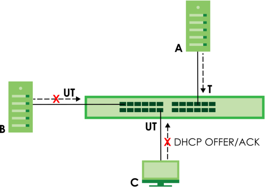
DHCP Snooping Status
Use this screen to look at various statistics about the DHCP snooping database.
The following table describes the labels in this screen.
label | description |
|---|---|
Database Status This section displays the current settings for the DHCP snooping database. You can configure them in the SECURITY > DHCP Snooping > DHCP Snp. Setup screen. | |
Agent URL | This field displays the location of the DHCP snooping database. |
Write Delay Timer | This field displays how long (in seconds) the Switch tries to complete a specific update in the DHCP snooping database before it gives up. |
Abort Timer | This field displays how long (in seconds) the Switch waits to update the DHCP snooping database after the current bindings change. |
Agent Running | This field displays the status of the current update or access of the DHCP snooping database. None: The Switch is not accessing the DHCP snooping database. Read: The Switch is loading dynamic bindings from the DHCP snooping database. Write: The Switch is updating the DHCP snooping database. |
Delay Timer Expiry | This field displays how much longer (in seconds) the Switch tries to complete the current update before it gives up. It displays Not Running if the Switch is not updating the DHCP snooping database right now. |
Abort Timer Expiry | This field displays when (in seconds) the Switch is going to update the DHCP snooping database again. It displays Not Running if the current bindings have not changed since the last update. |
Last Succeeded Time | This field displays the last time the Switch updated the DHCP snooping database successfully. |
Last Failed Time | This field displays the last time the Switch updated the DHCP snooping database unsuccessfully. |
Last Failed Reason | This field displays the reason the Switch updated the DHCP snooping database unsuccessfully. |
Counters This section displays historical information about the number of times the Switch successfully or unsuccessfully read or updated the DHCP snooping database. | |
Total Attempts | This field displays the number of times the Switch has tried to access the DHCP snooping database for any reason. |
Startup Failures | This field displays the number of times the Switch could not create or read the DHCP snooping database when the Switch started up or a new URL is configured for the DHCP snooping database. |
Successful Transfers | This field displays the number of times the Switch read bindings from or updated the bindings in the DHCP snooping database successfully. |
Failed Transfers | This field displays the number of times the Switch was unable to read bindings from or update the bindings in the DHCP snooping database. |
Successful Reads | This field displays the number of times the Switch read bindings from the DHCP snooping database successfully. |
Failed Reads | This field displays the number of times the Switch was unable to read bindings from the DHCP snooping database. |
Successful Writes | This field displays the number of times the Switch updated the bindings in the DHCP snooping database successfully. |
Failed Writes | This field displays the number of times the Switch was unable to update the bindings in the DHCP snooping database. |
Database Detail | |
First Successful Access | This field displays the first time the Switch accessed the DHCP snooping database for any reason. |
Last Ignored Bindings Counters This section displays the number of times and the reasons the Switch ignored bindings the last time it read bindings from the DHCP binding database. You can clear these counters by restarting the Switch. | |
Binding Collisions | This field displays the number of bindings the Switch ignored because the Switch already had a binding with the same MAC address and VLAN ID. |
Invalid Interfaces | This field displays the number of bindings the Switch ignored because the port number was a trusted interface or does not exist anymore. |
Parse Failures | This field displays the number of bindings the Switch ignored because the Switch was unable to understand the binding in the DHCP binding database. |
Expired Leases | This field displays the number of bindings the Switch ignored because the lease time had already expired. |
Unsupported VLANs | This field displays the number of bindings the Switch ignored because the VLAN ID does not exist anymore. |
Last Ignored Time | This field displays the last time the Switch ignored any bindings for any reason from the DHCP binding database. |
Total Ignored Bindings Counters This section displays the reasons the Switch has ignored bindings any time it read bindings from the DHCP binding database. You can clear these counters by restarting the Switch | |
Binding Collisions | This field displays the number of bindings the Switch has ignored because the Switch already had a binding with the same MAC address and VLAN ID. |
Invalid Interfaces | This field displays the number of bindings the Switch has ignored because the port number was a trusted interface or does not exist anymore. |
Parse Failures | This field displays the number of bindings the Switch has ignored because the Switch was unable to understand the binding in the DHCP binding database. |
Expired Leases | This field displays the number of bindings the Switch has ignored because the lease time had already expired. |
Unsupported VLANs | This field displays the number of bindings the Switch has ignored because the VLAN ID does not exist anymore. |
DHCP Snooping Setup
Use this screen to enable DHCP snooping on the Switch (not on specific VLAN), specify the VLAN where the default DHCP server is located, and configure the DHCP snooping database. The DHCP snooping database stores the current bindings on a secure, external TFTP server so that they are still available after a restart.
The following table describes the labels in this screen.
label | description |
|---|---|
DHCP Snooping Setup | |
Active | Enable the switch button to enable DHCP snooping on the Switch. You still have to enable DHCP snooping on specific VLAN and specify trusted ports. |
DHCP VLAN | Select a VLAN ID if you want the Switch to forward DHCP packets to DHCP servers on a specific VLAN. You can enable Option 82 Profile in the SECURITY > DHCP Snooping > DHCP Snp. VLAN Setup screento help the DHCP servers distinguish between DHCP requests from different VLAN. Select Disable if you do not want the Switch to forward DHCP packets to a specific VLAN. |
Database If Timeout Interval is greater than Write Delay Interval, it is possible that the next update is scheduled to occur before the current update has finished successfully or timed out. In this case, the Switch waits to start the next update until it completes the current one. | |
Agent URL | Enter the location of the DHCP snooping database. The location should be expressed like this: tftp://{domain name or IP address}/directory, if applicable/file name; for example, tftp://192.168.10.1/database.txt. You can enter up to 256 printable ASCII characters except [ ? ], [ | ], [ ' ], [ " ], or [ , ]. |
Timeout Interval | Enter how long (10 – 65535 seconds) the Switch tries to complete a specific update in the DHCP snooping database before it gives up. |
Write Delay Interval | Enter how long (10 – 65535 seconds) the Switch waits to update the DHCP snooping database the first time the current bindings change after an update. Once the next update is scheduled, additional changes in current bindings are automatically included in the next update. |
Renew DHCP Snooping URL | Enter the location of a DHCP snooping database, and click Renew if you want the Switch to load it. You can use this to load dynamic bindings from a different DHCP snooping database than the one specified in Agent URL. When the Switch loads dynamic bindings from a DHCP snooping database, it does not discard the current dynamic bindings first. If there is a conflict, the Switch keeps the dynamic binding in volatile memory and updates the Binding Collisions counter in the DHCP Snooping Status screen. |
Apply | Click Apply to save your changes to the Switch’s run-time memory. The Switch loses these changes if it is turned off or loses power, so use the Save link on the top navigation panel to save your changes to the non-volatile memory when you are done configuring. |
Cancel | Click this to reset the values in this screen to their last-saved values. |
DHCP Snooping Port Setup
Use this screen to specify whether ports are trusted or untrusted ports for DHCP snooping.
You can also specify the maximum number for DHCP packets that each port (trusted or untrusted) can receive each second.
The following table describes the labels in this screen.
label | description |
|---|---|
Port | This field displays the port number. |
* | Settings in this row apply to all ports. Use this row only if you want to make some settings the same for all ports. Use this row first to set the common settings and then make adjustments on a port-by-port basis. |
Server Trusted state | Select whether this port is a trusted port (Trusted) or an untrusted port (Untrusted). Trusted ports are connected to DHCP servers or other switches, and the Switch discards DHCP packets from trusted ports only if the rate at which DHCP packets arrive is too high. Untrusted ports are connected to subscribers, and the Switch discards DHCP packets from untrusted ports in the following situations: • The packet is a DHCP server packet (for example, OFFER, ACK, or NACK). • The source MAC address and source IP address in the packet do not match any of the current bindings. • The packet is a RELEASE or DECLINE packet, and the source MAC address and source port do not match any of the current bindings. • The rate at which DHCP packets arrive is too high. |
Rate (pps) | Specify the maximum number for DHCP packets (1 – 2048) that the Switch receives from each port each second. The Switch discards any additional DHCP packets. Enter 0 to disable this limit, which is recommended for trusted ports. |
Apply | Click Apply to save your changes to the Switch’s run-time memory. The Switch loses these changes if it is turned off or loses power, so use the Save link on the top navigation panel to save your changes to the non-volatile memory when you are done configuring. |
Cancel | Click this to reset the values in this screen to their last-saved values. |
DHCP Snooping VLAN Setup
Use this screen to enable DHCP snooping on each VLAN and to specify whether or not the Switch adds DHCP relay agent option 82 information to DHCP requests that the Switch relays to a DHCP server for each VLAN.
The following table describes the labels in this screen.
label | description |
|---|---|
Search VLAN by VID | Enter the VLAN ID you want to manage. Use a comma (,) to separate individual VLANs or a hyphen (-) to indicates a range of VLANs. For example, “3,4” or “3-9”. |
Search | Click this to display the specified range of VLANs in the section below. |
The Number of VLANs | This displays the number of VLAN search results. |
VID | This field displays the VLAN ID of each VLAN in the range specified above. If you configure the * VLAN, the settings are applied to all VLANs. |
Enabled | Select Yes to enable DHCP snooping on the VLAN. You still have to enable DHCP snooping on the Switch and specify trusted ports. |
Option 82 Profile | Select a pre-defined DHCP option 82 profile that the Switch applies to all ports in the specified VLANs. The Switch adds the information (such as slot number, port number, VLAN ID and/or system name) specified in the profile to DHCP requests that it broadcasts to the DHCP VLAN, if specified, or VLAN. You can specify the DHCP VLAN in the SECURITY > DHCP Snooping > DHCP Snp. Setup screen. |
Apply | Click Apply to save your changes to the Switch’s run-time memory. The Switch loses these changes if it is turned off or loses power, so use the Save link on the top navigation panel to save your changes to the non-volatile memory when you are done configuring. |
Cancel | Click this to reset the values in this screen to their last-saved values. |
DHCP Snooping VLAN Port Setup
Use this screen to apply a different DHCP option 82 profile to certain ports in a VLAN.
The following table describes the labels in this screen.
label | description |
|---|---|
Index | This field displays a sequential number for each entry. |
VID | This field displays the VLAN to which the ports belongs. |
Port | This field displays the ports to which the Switch applies the settings. |
Profile Name | This field displays the DHCP option 82 profile that the Switch applies to the ports. |
Add/Edit | Click Add/Edit to add a new entry or edit a selected one. |
Delete | Click Delete to remove the selected entries. |
Add/EDIT DHCP Snooping VLAN Ports
Use this screen to apply a different DHCP option 82 profile to certain ports in a VLAN.
Click Add/Edit, or select an entry and click Add/Edit in the SECURITY > IPv4 Source Guard > DHCP Snooping > DHCP Snp. VLAN Port Setup screen to display this screen.
The following table describes the labels in this screen.
label | description |
|---|---|
VID | Enter the ID number of the VLAN you want to configure here. |
Port | Enter the number of ports to which you want to apply the specified DHCP option 82 profile. You can enter multiple ports separated by (no space) comma (,) or hyphen (-) for a range. For example, enter “3-5” for ports 3, 4, and 5. Enter “3,5,7” for ports 3, 5, and 7. |
Option 82 Profile | Select a pre-defined DHCP option 82 profile that the Switch applies to the specified ports in this VLAN. The Switch adds the information (such as slot number, port number, VLAN ID and/or system name) specified in the profile to DHCP requests that it broadcasts to the DHCP VLAN, if specified, or VLAN. You can specify the DHCP VLAN in the SECURITY > DHCP Snooping > DHCP Snp. Setup screen. |
Apply | Click Apply to save your changes to the Switch’s run-time memory. The Switch loses these changes if it is turned off or loses power, so use the Save link on the top navigation panel to save your changes to the non-volatile memory when you are done configuring. |
Clear | Click Clear to clear the fields to the factory defaults. |
Cancel | Click Cancel to not save the configuration you make and return to the last screen. |
ARP Inspection Status
Use this screen to look at the current list of MAC address filters that were created because the Switch identified an unauthorized ARP packet. When the Switch identifies an unauthorized ARP packet, it automatically creates a MAC address filter to block traffic from the source MAC address and source VLAN ID of the unauthorized ARP packet.
The following table describes the labels in this screen.
label | description |
|---|---|
Total Number of Bindings | This field displays the current number of MAC address filters that were created because the Switch identified unauthorized ARP packets. |
Index | This field displays a sequential number for each MAC address filter. |
MAC Address | This field displays the source MAC address in the MAC address filter. |
VID | This field displays the source VLAN ID in the MAC address filter. |
Port | This field displays the source port of the discarded ARP packet. |
Expiry (sec) | This field displays how long (in seconds) the MAC address filter remains in the Switch. You can also delete the record manually (Delete). |
Select an entry’s checkbox to select a specific entry. Otherwise, select the checkbox in the table heading row to select all entries. | |
Delete | Click this to remove the selected entries. |
Cancel | Click this to clear the Delete checkboxes above. |
ARP Inspection VLAN Status
Use this screen to look at various statistics about ARP packets in each VLAN.
The following table describes the labels in this screen.
label | description |
|---|---|
Search VLAN by VID | Specify the VLANs you want to view in the section below. Use a comma (,) to separate individual VLANs or a hyphen (-) to indicates a range of VLANs. For example, “3,4” or “3-9”. |
Search | Click this to display the specified range of VLANs in the section below. |
The Number of VLANs | This is the number of VLANs that match the searching criteria and display in the list below. The number displays when you use the Search button to look for certain VLANs. The default value is 0. |
VID | This field displays the VLAN ID of each VLAN in the range specified above. |
Received | This field displays the total number of ARP packets received from the VLAN since the Switch last restarted. |
Request | This field displays the total number of ARP Request packets received from the VLAN since the Switch last restarted. |
Reply | This field displays the total number of ARP Reply packets received from the VLAN since the Switch last restarted. |
Forwarded | This field displays the total number of ARP packets the Switch forwarded for the VLAN since the Switch last restarted. |
Dropped | This field displays the total number of ARP packets the Switch discarded for the VLAN since the Switch last restarted. |
ARP Inspection Log Status
Use this screen to look at log messages that were generated by ARP packets and that have not been sent to the syslog server yet.
The following table describes the labels in this screen.
label | description |
|---|---|
Clearing Log Status Table | Click Clear to remove all the log messages that were generated by ARP packets and that have not been sent to the syslog server yet. |
Total number of Bindings | This field displays the number of log messages that were generated by ARP packets and that have not been sent to the syslog server yet. If one or more log messages are dropped due to unavailable buffer, there is an entry called overflow with the current number of dropped log messages. |
Index | This field displays a sequential number for each log message. |
Port | This field displays the source port of the ARP packet. |
VID | This field displays the source VLAN ID of the ARP packet. |
Sender MAC | This field displays the source MAC address of the ARP packet. |
Sender IP | This field displays the source IP address of the ARP packet. |
Packet Number | This field displays the number of ARP packets that were consolidated into this log message. The Switch consolidates identical log messages generated by ARP packets in the log consolidation interval into one log message. You can configure this interval in the SECURITY > IPv4 Source Guard > ARP Inspection > ARP Insp. Setup screen. |
Reason | This field displays the reason the log message was generated. dhcp deny: An ARP packet was discarded because it violated a dynamic binding with the same MAC address and VLAN ID. static deny: An ARP packet was discarded because it violated a static binding with the same MAC address and VLAN ID. deny: An ARP packet was discarded because there were no bindings with the same MAC address and VLAN ID. dhcp permit: An ARP packet was forwarded because it matched a dynamic binding. static permit: An ARP packet was forwarded because it matched a static binding. In the SECURITY > IPv4 Source Guard > ARP Inspection > ARP Insp. VLAN Setup screen, you can configure the Switch to generate log messages when ARP packets are discarded or forwarded based on the VLAN ID of the ARP packet. |
Time | This field displays when the log message was generated. |
ARP Inspection Setup
Use this screen to enable ARP inspection on the Switch. You can also configure the length of time the Switch stores records of discarded ARP packets and global settings for the ARP inspection log.
The following table describes the labels in this screen.
label | description |
|---|---|
ARP Inspection Setup | |
Active | Enable the switch button to enable ARP inspection on the Switch. You still have to enable ARP inspection on specific VLAN and specify trusted ports. |
Filter Aging Time | |
Filter Aging Time | This setting has no effect on existing MAC address filters. Enter how long (1 – 2147483647 seconds) the MAC address filter remains in the Switch after the Switch identifies an unauthorized ARP packet. The Switch automatically deletes the MAC address filter afterwards. Type 0 if you want the MAC address filter to be permanent. |
Log Profile | |
Log Buffer Size | Enter the maximum number (1 – 1024) of log messages that were generated by ARP packets and have not been sent to the syslog server yet. Make sure this number is appropriate for the specified Syslog Rate and Log Interval. If the number of log messages in the Switch exceeds this number, the Switch stops recording log messages and simply starts counting the number of entries that were dropped due to unavailable buffer. Click Clearing Log Status Table in the SECURITY > IPv4 Source Guard > ARP Inspection > ARP Insp. Log Status screen to clear the log and reset this counter. |
Syslog Rate | Type the maximum number of syslog messages the Switch can send to the syslog server in one batch. This number is expressed as a rate because the batch frequency is determined by the Log Interval. You must configure the syslog server to use this. Enter 0 if you do not want the Switch to send log messages generated by ARP packets to the syslog server. The relationship between Syslog Rate and Log Interval is illustrated in the following examples: • Four invalid ARP packets per second, Syslog Rate is 5, Log Interval is 1: the Switch sends 4 syslog messages every second. • Six invalid ARP packets per second, Syslog Rate is 5, Log Interval is 2: the Switch sends 5 syslog messages every 2 seconds. |
Log interval | Type how often (1 – 86400 seconds) the Switch sends a batch of syslog messages to the syslog server. Enter 0 if you want the Switch to send syslog messages immediately. See Syslog Rate for an example of the relationship between Syslog Rate and Log Interval. |
Apply | Click Apply to save your changes to the Switch’s run-time memory. The Switch loses these changes if it is turned off or loses power, so use the Save link on the top navigation panel to save your changes to the non-volatile memory when you are done configuring. |
Cancel | Click this to reset the values in this screen to their last-saved values. |
ARP Inspection Port Setup
Use this screen to specify whether ports are trusted or untrusted ports for ARP inspection. You can also specify the maximum rate at which the Switch receives ARP packets on each untrusted port.
The following table describes the labels in this screen.
label | description |
|---|---|
Port | This field displays the port number. |
* | Settings in this row apply to all ports. Use this row only if you want to make some settings the same for all ports. Use this row first to set the common settings and then make adjustments on a port-by-port basis. |
Trusted State | Select whether this port is a trusted port (Trusted) or an untrusted port (Untrusted). The Switch does not discard ARP packets on trusted ports for any reason. The Switch discards ARP packets on untrusted ports in the following situations: • The sender’s information in the ARP packet does not match any of the current bindings. • The rate at which ARP packets arrive is too high. You can specify the maximum rate at which ARP packets can arrive on untrusted ports. |
Limit | Rate and Burst Interval settings have no effect on trusted ports. |
Rate (pps) | Specify the maximum rate (1 – 2048 packets per second) at which the Switch receives ARP packets from each port. The Switch discards any additional ARP packets. Enter 0 to disable this limit. |
Burst Interval (seconds) | The burst interval is the length of time over which the rate of ARP packets is monitored for each port. For example, if the Rate is 15 pps and the burst interval is 1 second, then the Switch accepts a maximum of 15 ARP packets in every one-second interval. If the burst interval is 5 seconds, then the Switch accepts a maximum of 75 ARP packets in every five-second interval. Enter the length (1 – 15 seconds) of the burst interval. |
Apply | Click Apply to save your changes to the Switch’s run-time memory. The Switch loses these changes if it is turned off or loses power, so use the Save link on the top navigation panel to save your changes to the non-volatile memory when you are done configuring. |
Cancel | Click this to reset the values in this screen to their last-saved values. |
ARP Inspection VLAN Setup
Use this screen to enable ARP inspection on each VLAN and to specify when the Switch generates log messages for receiving ARP packets from each VLAN.
The following table describes the labels in this screen.
label | description |
|---|---|
Search VLAN by VID | Specify the VLANs you want to manage in the section below. Use a comma (,) to separate individual VLANs or a hyphen (-) to indicates a range of VLANs. For example, “3,4” or “3-9”. |
Search | Click this to display the specified range of VLANs in the section below. |
The Number of VLANs | This display the number of ARP inspection VLAN search results. |
VID | This field displays the VLAN ID of each VLAN in the range specified above. If you configure the * VLAN, the settings are applied to all VLANs. |
Enabled | Select Yes to enable ARP inspection on the VLAN. Select No to disable ARP inspection on the VLAN. |
Log | Specify when the Switch generates log messages for receiving ARP packets from the VLAN. None: The Switch does not generate any log messages when it receives an ARP packet from the VLAN. Deny: The Switch generates log messages when it discards an ARP packet from the VLAN. Permit: The Switch generates log messages when it forwards an ARP packet from the VLAN. All: The Switch generates log messages every time it receives an ARP packet from the VLAN. |
Apply | Click Apply to save your changes to the Switch’s run-time memory. The Switch loses these changes if it is turned off or loses power, so use the Save link on the top navigation panel to save your changes to the non-volatile memory when you are done configuring. |
Cancel | Click this to reset the values in this screen to their last-saved values. |
Port Authentication Overview
Port authentication is a way to validate access to ports on the Switch to clients based on an external authentication server. The Switch supports the following methods for port authentication:
• IEEE 802.1x – An authentication server validates access to a port based on a user name and password provided by the user. A user that fails an authentication server can still access the port, but traffic from the user is forwarded to the guest VLAN port.
• MAC Authentication – An authentication server validates access to a port based on the MAC address and password of the client.
• Guest VLAN – In either mode, if authentication fails the Switch can still allow the client to access the network on a Guest VLAN.
IEEE 802.1x Security
Use this screen to activate IEEE 802.1x security.
The following table describes the labels in this screen.
label | description |
|---|---|
Active | Enable the switch button to permit 802.1x authentication on the Switch. |
Port | This field displays the port number. * means all ports. |
* | Settings in this row apply to all ports. Use this row only if you want to make some settings the same for all ports. Use this row first to set the common settings and then make adjustments on a port-by-port basis. |
Active | Select this to permit 802.1x authentication on this port. You must first allow 802.1x authentication on the Switch before configuring it on each port. |
Max-Req | Specify the number of times the Switch tries to authenticate clients before sending unresponsive ports to the Guest VLAN. This is set to 2 by default. That is, the Switch attempts to authenticate a client twice. If the client does not respond to the first authentication request, the Switch tries again. If the client still does not respond to the second request, the Switch sends the client to the Guest VLAN. The client needs to send a new request to be authenticated by the Switch again. |
Reauth | Specify if a subscriber has to periodically re-enter his or her user name and password to stay connected to the port. |
Reauth-period secs | Specify the length of time required to pass before a client has to re-enter his or her user name and password to stay connected to the port. |
Quiet-period secs | Specify the number of seconds the port remains in the HELD state and rejects further authentication requests from the connected client after a failed authentication exchange. |
Tx-period secs | Specify the number of seconds the Switch waits for client’s response before re-sending an identity request to the client. |
Supp-Timeout secs | Specify the number of seconds the Switch waits for client’s response to a challenge request before sending another request. |
Apply | Click Apply to save your changes to the Switch’s run-time memory. The Switch loses these changes if it is turned off or loses power, so use the Save link on the top navigation panel to save your changes to the non-volatile memory when you are done configuring. |
Cancel | Click Cancel to begin configuring this screen afresh. |
MAC Authentication
Use this screen to activate MAC authentication.
The following table describes the labels in this screen.
label | description |
|---|---|
Active | Enable the switch button to permit MAC authentication on the Switch. |
Name Prefix | Type the prefix that is appended to all MAC addresses sent to the RADIUS server for authentication. You can enter up to 32 printable ASCII characters except [ ? ], [ | ], [ ' ], [ " ], [ , ]. If you leave this field blank, then only the MAC address of the client is forwarded to the RADIUS server. |
Delimiter | Select the delimiter the RADIUS server uses to separate the pairs in MAC addresses used as the account user name (and password). You can select Dash (–), Colon (:), or None to use no delimiters at all in the MAC address. |
Case | Select the case (Upper or Lower) the RADIUS server requires for letters in MAC addresses used as the account user name (and password). |
Password Type | Select Static to have the Switch send the password you specify below or MAC-Address to use the client MAC address as the password. |
Password | Type the password the Switch sends along with the MAC address of a client for authentication with the RADIUS server. You can enter up to 32 printable ASCII characters except [ ? ], [ | ], [ ' ], [ " ], or [ , ]. |
Timeout | Specify the amount of time (in seconds) before the Switch allows a client MAC address that fails authentication to try and authenticate again. Maximum time is 3000 seconds. When a client fails MAC authentication, its MAC address is learned by the MAC address table with a status of denied. The timeout period you specify here is the time the MAC address entry stays in the MAC address table until it is cleared. If you specify 0 for the timeout value, the Switch uses the Aging Time configured in the SYSTEM > Switch Setup > Switch Setup screen. |
Port | This field displays a port number. * means all ports. |
* | Use this row to make the setting the same for all ports. Use this row first and then make adjustments on a port-by-port basis. |
Active | Select this checkbox to permit MAC authentication on this port. You must first allow MAC authentication on the Switch before configuring it on each port. |
Apply | Click Apply to save your changes to the Switch’s run-time memory. The Switch loses these changes if it is turned off or loses power, so use the Save link on the top navigation panel to save your changes to the non-volatile memory when you are done configuring. |
Cancel | Click Cancel to begin configuring this screen afresh. |
Guest VLAN
When 802.1x or MAC Authentication is enabled on the Switch and its ports, clients that do not have the correct credentials are blocked from using the ports. You can configure your Switch to have one VLAN that acts as a guest VLAN. If you enable the guest VLAN on a port , the user that is not IEEE 802.1x capable or fails to enter the correct user name and password can still access the port, but traffic from the user is forwarded to the guest VLAN. That is, unauthenticated users can have access to limited network resources in the same guest VLAN, such as the Internet. The access granted to the Guest VLAN depends on how the network administrator configures switches or routers with the guest network feature.
Use this screen to enable and assign a guest VLAN to a port.
The following table describes the labels in this screen.
label | description |
|---|---|
Port | This field displays a port number. * means all ports. |
* | Settings in this row apply to all ports. Use this row only if you want to make some settings the same for all ports. Use this row first to set the common settings and then make adjustments on a port-by-port basis. Changes in this row are copied to all the ports as soon as you make them. |
Active | Select this checkbox to enable the guest VLAN feature on this port. Clients that fail authentication are placed in the guest VLAN and can receive limited services. |
Guest VLAN | A guest VLAN is a pre-configured VLAN on the Switch that allows non-authenticated users to access limited network resources through the Switch. You must also enable IEEE 802.1x authentication on the Switch and the associated ports. Enter the number that identifies the guest VLAN. Make sure this is a VLAN recognized in your network. |
Host-mode | Specify how the Switch authenticates users when more than one user connect to the port (using a hub). Select Multi-Host to authenticate only the first user that connects to this port. If the first user enters the correct credential, any other users are allowed to access the port without authentication. If the first user fails to enter the correct credential, they are all put in the guest VLAN. Once the first user who did authentication logs out or disconnects from the port, the rest of the users are blocked until a user does the authentication process again. Select Multi-Secure to authenticate each user that connects to this port. |
Multi-secure Num | If you set Host-mode to Multi-Secure, specify the maximum number of users (between 1 and 5) that the Switch will authenticate on this port. |
Apply | Click Apply to save your changes to the Switch’s run-time memory. The Switch loses these changes if it is turned off or loses power, so use the Save link on the top navigation panel to save your changes to the non-volatile memory when you are done configuring. |
Cancel | Click Cancel to begin configuring this screen afresh. |
Port Security Overview
Port security allows only packets with dynamically learned MAC addresses and/or configured static MAC addresses to pass through a port on the Switch.
For maximum port security, enable this feature, disable MAC address learning and configure static MAC addresses for a port.
Port Security
The following table describes the labels in this screen.
label | description |
|---|---|
MAC Freeze | |
Port List | Enter the number of the ports (separated by a comma) on which you want to enable port security and disable MAC address learning. After you click MAC Freeze, all previously learned MAC addresses on the specified ports will become static MAC addresses and display in the SWITCHING > Static MAC Forwarding > Static MAC Forwarding screen. |
MAC Freeze | Click MAC Freeze to have the Switch automatically select the Active checkboxes and clear the Address Learning checkboxes only for the ports specified in the Port List. |
Port Security | |
Active | Enable the switch button to enable port security on the Switch. |
Port | This field displays the port number. |
* | Settings in this row apply to all ports. Use this row only if you want to make some of the settings the same for all ports. Use this row first to set the common settings and then make adjustments on a port-by-port basis. |
Active | Select this checkbox to enable the port security feature on this port. The Switch forwards packets whose MAC addresses is in the MAC address table on this port. Packets with no matching MAC addresses are dropped. Clear this checkbox to disable the port security feature. The Switch forwards all packets on this port. |
Address Learning | MAC address learning reduces outgoing broadcast traffic. For MAC address learning to occur on a port, the port itself must be active with address learning enabled. |
Limited Number of Learned MAC Address | Use this field to limit the number of (dynamic) MAC addresses that may be learned on a port. For example, if you set this field to "5" on port 2, then only the devices with these five learned MAC addresses may access port 2 at any one time. A sixth device must wait until one of the five learned MAC addresses ages out. MAC address aging out time can be set in the SYSTEM > Switch Setup screen. The valid range is from “0” to “32K”. “0” means this feature is disabled. |
Apply | Click Apply to save your changes to the Switch’s run-time memory. The Switch loses these changes if it is turned off or loses power, so use the Save link on the top navigation panel to save your changes to the non-volatile memory when you are done configuring. |
Cancel | Click Cancel to begin configuring this screen afresh. |