SWITCHING
The following sections introduce the SWITCHING screens.
Differentiated Services
DiffServ is a class of service (CoS) model that marks packets so that they receive specific per-hop treatment at DiffServ-compliant network devices along the route based on the application types and traffic flow. Packets are marked with DiffServ Code Points (DSCPs) indicating the level of service desired. This allows the intermediary DiffServ-compliant network devices to handle the packets differently depending on the code points without the need to negotiate paths or remember state information for every flow. In addition, applications do not have to request a particular service or give advanced notice of where the traffic is going.
Activate DiffServ to apply marking rules or IEEE 802.1p priority mapping on the selected ports.
The following table describes the labels in this screen.
label | description |
|---|---|
Active | Enable the switch button to enable Diffserv on the Switch. |
Port | This field displays the index number of a port on the Switch. |
* | Settings in this row apply to all ports. Use this row only if you want to make some settings the same for all ports. Use this row first to set the common settings and then make adjustments on a port-by-port basis. Changes in this row are copied to all the ports as soon as you make them. |
Active | Select Active to enable Diffserv on the port. |
Apply | Click Apply to save your changes to the Switch’s run-time memory. The Switch loses these changes if it is turned off or loses power, so use the Save link on the top navigation panel to save your changes to the non-volatile memory when you are done configuring. |
Cancel | Click Cancel to begin configuring this screen afresh. |
DSCP-to-IEEE 802.1p Priority Settings
You can configure the DSCP to IEEE 802.1p mapping to allow the Switch to prioritize all traffic based on the incoming DSCP value according to the DiffServ to IEEE 802.1p mapping table.
The following table shows the default DSCP-to-IEEE802.1p mapping.
DSCP VALUE | 0 – 7 | 8 – 15 | 16 – 23 | 24 – 31 | 32 – 39 | 40 – 47 | 48 – 55 | 56 – 63 |
IEEE 802.1p | 0 | 1 | 2 | 3 | 4 | 5 | 6 | 7 |
The following table describes the labels in this screen.
label | description |
|---|---|
0 … 63 | This is the DSCP classification identification number. To set the IEEE 802.1p priority mapping, select the priority level from the drop-down list box. |
Apply | Click Apply to save your changes to the Switch’s run-time memory. The Switch loses these changes if it is turned off or loses power, so use the Save link on the top navigation panel to save your changes to the non-volatile memory when you are done configuring. |
Cancel | Click Cancel to begin configuring this screen afresh. |
Port Mirroring
Port mirroring allows you to copy a traffic flow to a monitor port (the port you copy the traffic to) in order that you can examine the traffic from the monitor port without interference.
Use this screen to select a monitor port and specify the traffic flow to be copied to the monitor port.
The following table describes the labels in this screen.
LABEL | DESCRIPTION |
|---|---|
Active | Enable the switch button to activate port mirroring on the Switch. Disable the switch to disable the feature. |
Monitor Port | The monitor port is the port you copy the traffic to in order to examine it in more detail without interfering with the traffic flow on the original ports. Enter the port number of the monitor port. |
Port | This field displays the port number. |
* | Settings in this row apply to all ports. Use this row only if you want to make some settings the same for all ports. Use this row first to set the common settings and then make adjustments on a port-by-port basis. |
Mirrored | Select this option to mirror the traffic on a port. |
Direction | Specify the direction of the traffic to mirror by selecting from the drop-down list box. Choices are Egress (outgoing), Ingress (incoming) and Both. |
Apply | Click Apply to save your changes to the Switch’s run-time memory. The Switch loses these changes if it is turned off or loses power, so use the Save link on the top navigation panel to save your changes to the non-volatile memory when you are done configuring. |
Cancel | Click Cancel to reset the fields. |
Multicast
Traditionally, IP packets are transmitted in one of either two ways – Unicast (1 sender to 1 recipient) or Broadcast (1 sender to everybody on the network). Multicast delivers IP packets to just a group of hosts on the network.
IGMP (Internet Group Management Protocol) is a network-layer protocol used to establish membership in a multicast group – it is not used to carry user data. Refer to RFC 1112, RFC 2236 and RFC 3376 for information on IGMP versions 1, 2 and 3 respectively.
This section shows you how to configure various multicast features.
What You Can Do
• Use the IGMP Snooping screen (IGMP Snooping) to enable IGMP snooping to forward group multicast traffic only to ports that are members of that group.
• Use the IGMP Snooping VLAN screen (IGMP Snooping VLAN) to perform IGMP snooping on up to 16 VLANs.
• Use the IGMP Filtering Profile screen (IGMP Filtering Profile) to specify a range of multicast groups that clients connected to the Switch are able to join.
IPv4 Multicast Status
This screen shows the IPv4 multicast group information.
The following table describes the labels in this screen.
label | description |
|---|---|
Index | This is the index number of the entry. |
VID | This field displays the multicast VLAN ID. |
Port | This field displays the port number that belongs to the multicast group. |
Multicast Group | This field displays IP multicast group addresses. |
IGMP Snooping
A Switch can passively snoop on IGMP packets transferred between IP multicast routers or switches and IP multicast hosts to learn the IP multicast group membership. It checks IGMP packets passing through it, picks out the group registration information, and configures multicasting accordingly. IGMP snooping allows the Switch to learn multicast groups without you having to manually configure them.
The Switch forwards multicast traffic destined for multicast groups (that it has learned from IGMP snooping or that you have manually configured) to ports that are members of that group. IGMP snooping generates no additional network traffic, allowing you to significantly reduce multicast traffic passing through your Switch.
The following table describes the labels in this screen.
label | description |
|---|---|
Active | Enable the switch button to enable IGMP Snooping to forward group multicast traffic only to ports that are members of that group. |
Querier | Select this to allow the Switch to send IGMP General Query messages to the VLANs with the multicast hosts attached. |
Querier Version | IGMP snooping query works only when both host and Switch support the same IGMP version. Select v2 to allow the Switch to send IGMPv2 queries only. Select v3 to allow the Switch to send IGMPv3 queries only. |
Querier Query Interval | Enter the period in seconds (1 to 65535) between each IGMP snooping query. The Switch sends IGMP General Query messages after every query interval. |
Report Proxy | Select this to allow the Switch to act as the IGMP report proxy and leave proxy. It will report group changes to a connected multicast router. The Switch not only checks IGMP packets between multicast routers or switches and multicast hosts to learn the multicast group membership, but also replaces the source MAC address in an IGMP v1/v2 report with its own MAC address before forwarding to the multicast router or switch. When the Switch receives more than one IGMP v1/v2 join report that requests to join the same multicast group, it only sends a new join report with its MAC address. This helps reduce the number of multicast join reports passed to the multicast router or switch. The Switch sends a leave message with its MAC address to the multicast router or switch only when it receives the leave message from the last host in a multicast group. |
Host Timeout | Specify the time (from 1 to 16711450) in seconds that elapses before the Switch removes an IGMP group membership entry if it does not receive report messages from the port. |
802.1p Priority | Select a priority level (0 – 7) to which the Switch changes the priority in outgoing IGMP control packets. Otherwise, select No-Change to not replace the priority. |
IGMP Filtering Active | Enable the switch button to enable IGMP filtering to control which IGMP groups a subscriber on a port can join. If you enable IGMP filtering, you must create and assign IGMP filtering profiles for the ports that you want to allow to join multicast groups. |
IGMP Snooping Smart Forward Active | Enable the switch button to enable sending of multicast frame to querier port and IGMP subscriber groups. Otherwise, the querier port forwards the frames only when it receives a join report and it belongs to the IGMP group. |
Unknown Multicast Frame | Specify the action to perform when the Switch receives an unknown multicast frame. • Select Flooding to send the frames to all ports. • Select Drop to discard the frames. • Select Drop on VLAN and enter the VLAN ID numbers to discard the frames on the specified VLANs. Use a dash to specify consecutive VLANs and a comma (no spaces) to specify non-consecutive VLANs. For example, 51–53 includes 51, 52 and 53, but 51,53 does not include 52. |
Unknown Multicast Frame to Querier Port | Specify the action to perform when Unknown Multicast Frame is set to Drop. • Select Drop to discard the frames. • Select Forwarding to send the frames to all querier ports. • Select Forwarding on VLAN and enter the VLAN ID numbers to send the frames to the ports which are used as an IGMP query port on the specified VLANs. Use a dash to specify consecutive VLANs and a comma (no spaces) to specify non-consecutive VLANs. For example, 51–53 includes 51, 52 and 53, but 51,53 does not include 52. |
Reserved Multicast Group | The IP address range of 224.0.0.0 to 224.0.0.255 are reserved for multicasting on the local network only. For example, 224.0.0.1 is for all hosts on a local network segment and 224.0.0.9 is used to send RIP routing information to all RIP v2 routers on the same network segment. A multicast router will not forward a packet with the destination IP address within this range to other networks. See the IANA web site for more information. The layer-2 multicast MAC addresses used by Cisco layer-2 protocols, 01:00:0C:CC:CC:CC and 01:00:0C:CC:CC:CD, are also included in this group. Specify the action to perform when the Switch receives a frame with a reserved multicast address. • Select Flooding to send the frames to all ports. • Select Drop to discard the frames. |
Use this section to configure IGMP Snooping on each port. | |
Port | This field displays the port number. |
* | Settings in this row apply to all ports. Use this row only if you want to make some settings the same for all ports. Use this row first to set the common settings and then make adjustments on a port-by-port basis. Changes in this row are copied to all the ports as soon as you make them. |
Immediate Leave | Select this option to set the Switch to remove this port from the multicast tree when an IGMP version 2 leave message is received on this port. Select this option if there is only one host connected to this port. |
Normal Leave | Enter an IGMP normal leave timeout value (from 200 to 6348800) in miliseconds. Select this option to have the Switch use this timeout to update the forwarding table for the port. In normal leave mode, when the Switch receives an IGMP leave message from a host on a port, it forwards the message to the multicast router. The multicast router then sends out an IGMP Group-Specific Query (GSQ) message to determine whether other hosts connected to the port should remain in the specific multicast group. The Switch forwards the query message to all hosts connected to the port and waits for IGMP reports from hosts to update the forwarding table. This defines how many seconds the Switch waits for an IGMP report before removing an IGMP snooping membership entry when an IGMP leave message is received on this port from a host. |
Fast Leave | Enter an IGMP fast leave timeout value (from 200 to 6348800) in miliseconds. Select this option to have the Switch use this timeout to update the forwarding table for the port. In fast leave mode, right after receiving an IGMP leave message from a host on a port, the Switch itself sends out an IGMP Group-Specific Query (GSQ) message to determine whether other hosts connected to the port should remain in the specific multicast group. This helps speed up the leave process. This defines how many seconds the Switch waits for an IGMP report before removing an IGMP snooping membership entry when an IGMP leave message is received on this port from a host. |
Group Limited | Select this option to limit the number of multicast groups this port is allowed to join. |
Max Group Number | Enter the number of multicast groups this port is allowed to join. Once a port is registered in the specified number of multicast groups, any new IGMP join report frames is dropped on this port. |
Throttling | IGMP throttling controls how the Switch deals with the IGMP reports when the maximum number of the IGMP groups a port can join is reached. Select Deny to drop any new IGMP join report received on this port until an existing multicast forwarding table entry is aged out. Select Replace to replace an existing entry in the multicast forwarding table with the new IGMP reports received on this port. |
IGMP Filtering Profile | Select the name of the IGMP filtering profile to use for this port. Otherwise, select Default to prohibit the port from joining any multicast group. You can create IGMP filtering profiles in the SWITCHING > Multicast > IPv4 Multicast > IGMP Filtering Profile screen. |
IGMP Querier Mode | The Switch treats an IGMP query port as being connected to an IGMP multicast router (or server). The Switch forwards IGMP join or leave packets to an IGMP query port. Select Auto to have the Switch use the port as an IGMP query port if the port receives IGMP query packets. Select Fixed to have the Switch always use the port as an IGMP query port. Select this when you connect an IGMP multicast server to the port. Select Edge to stop the Switch from using the port as an IGMP query port. The Switch will not keep any record of an IGMP router being connected to this port. The Switch does not forward IGMP join or leave packets to this port. |
Apply | Click Apply to save your changes to the Switch’s run-time memory. The Switch loses these changes if it is turned off or loses power, so use the Save link on the top navigation panel to save your changes to the non-volatile memory when you are done configuring. |
Cancel | Click Cancel to begin configuring this screen afresh. |
IGMP Snooping VLAN
You can configure the Switch to automatically learn multicast group membership of any VLANs. The Switch then performs IGMP snooping on the first 16 VLANs that send IGMP packets. This is referred to as auto mode. Alternatively, you can specify the VLANs that IGMP snooping should be performed on. This is referred to as fixed mode. In fixed mode the Switch does not learn multicast group membership of any VLANs other than those explicitly added as an IGMP snooping VLAN.
The following table describes the labels in this screen.
label | description |
|---|---|
IGMP Snooping VLAN | |
Mode | Select auto to have the Switch learn multicast group membership information of any VLANs automatically. Select fixed to have the Switch only learn multicast group membership information of the VLANs that you specify below. In either auto or fixed mode, the Switch can learn up to 16 VLANs. The Switch drops any IGMP control messages which do not belong to these 16 VLANs. You must also enable IGMP snooping in the SWITCHING > Multicast > IGMP Snooping screen first. |
Apply | Click Apply to save your changes to the Switch’s run-time memory. The Switch loses these changes if it is turned off or loses power, so use the Save link on the top navigation panel to save your changes to the non-volatile memory when you are done configuring. |
Cancel | Click Cancel to begin configuring this screen afresh. |
VLAN Use this section of the screen to add VLANs on which the Switch is to perform IGMP snooping. | |
Index | This is the index number of the IGMP snooping VLAN entry in the table. |
Name | This field displays the descriptive name for this VLAN group. |
VID | This field displays the ID number of the VLAN group. |
Select an entry’s checkbox to select a specific entry. Otherwise, select the checkbox in the table heading row to select all entries. | |
Add/Edit | Click Add/Edit to create a new entry or edit a selected one. |
Delete | Click Delete to remove the selected entries. |
Add/Edit IGMP Snooping VLANs
This screen allows you to add an IGMP snooping VLAN or edit an existing one.
To access this screen, click the Add/Edit button or select an entry from the list and click the Add/Edit button.
The following table describes the labels in this screen.
label | description |
|---|---|
Name | Enter the descriptive name (up to 32 printable ASCII characters except [ ? ], [ | ], [ ' ], [ " ], or [ , ]) of the VLAN for identification purposes. |
VID | Enter the ID of a static VLAN; the valid range is between 1 and 4094. |
Apply | Click Apply to save your changes to the Switch’s run-time memory. The Switch loses these changes if it is turned off or loses power, so use the Save link on the top navigation panel to save your changes to the non-volatile memory when you are done configuring. |
Clear | Click Clear to clear the fields to the factory defaults. |
Cancel | Click Cancel to not save the configuration you make and return to the last screen. |
IGMP Filtering Profile
An IGMP filtering profile specifies a range of multicast groups that clients connected to the Switch are able to join. A profile contains a range of multicast IP addresses which you want clients to be able to join. Profiles are assigned to ports (in the SWITCHING > Multicast > IPv4 Multicast > IGMP Snooping screen). Clients connected to those ports are then able to join the multicast groups specified in the profile. Each port can be assigned a single profile. A profile can be assigned to multiple ports.
The following table describes the labels in this screen.
label | description |
|---|---|
Profile Name | This field displays the descriptive name of the profile. |
Start Address | This field displays the start of the multicast address range. |
End Address | This field displays the end of the multicast address range. |
Select an entry’s checkbox to select a specific entry. Otherwise, select the checkbox in the table heading row to select all entries. | |
Add Profile | Click this to add a new IGMP filtering profile. |
Add Rule | Click Add Rule to add a new rule and specify the profile it belongs to in the Add Rule screen. You can also select a profile entry and click Add Rule to add an additional rule for the selected profile. |
Delete | Select a profile and click Delete to remove the selected profile and the accompanying rules. Select a rule from a profile and click Delete to remove the selected rule. |
Add IGMP Filtering Profile
To access this screen, click the Add Profile button in the SWITCHING > Multicast > IPv4 Multicast > IGMP Filtering Profile screen.
The following table describes the labels in this screen.
label | description |
|---|---|
Profile Name | Enter a descriptive name for the profile for identification purposes. You can enter up to 32 printable ASCII characters except [ ? ], [ | ], [ ' ], [ " ], or [ , ]. |
Start Address | Enter the starting multicast IP address for a range of multicast IP addresses that you want to belong to the IGMP filter profile. |
End Address | Enter the ending multicast IP address for a range of IP addresses that you want to belong to the IGMP filter profile. If you want to add a single multicast IP address, enter it in both the Start Address and End Address fields. |
Apply | Click Apply to save your changes to the Switch’s run-time memory. The Switch loses these changes if it is turned off or loses power, so use the Save link on the top navigation panel to save your changes to the non-volatile memory when you are done configuring. |
Clear | Click Clear to clear the fields to the factory defaults. |
Cancel | Click Cancel to not save the configuration you make and return to the last screen. |
Add IGMP Filtering Rule
Click Add Rule in the SWITCHING > Multicast > IPv4 Multicast > IGMP Filtering Profile screen to access this screen.
The following table describes the labels in this screen.
label | description |
|---|---|
Profile Name | Select a profile from the drop-down list to add a additional rule for the existing profile. |
Start Address | Enter the starting multicast IP address for a range of multicast IP addresses that you want to belong to the IGMP filter profile. |
End Address | Enter the ending multicast IP address for a range of IP addresses that you want to belong to the IGMP filter profile. If you want to add a single multicast IP address, enter it in both the Start Address and End Address fields. |
Apply | Click Apply to save your changes to the Switch’s run-time memory. The Switch loses these changes if it is turned off or loses power, so use the Save link on the top navigation panel to save your changes to the non-volatile memory when you are done configuring. |
Clear | Click Clear to clear the fields to the factory defaults. |
Cancel | Click Cancel to not save the configuration you make and return to the last screen. |
Static Multicast Forwarding By MAC
Use this screen to view and configure static multicast MAC addresses for ports to receive the multicast stream.
The following table describes the labels in this screen.
label | description |
|---|---|
Index | This is the index number of the static multicast MAC address rule. |
Active | This field displays whether a static multicast MAC address forwarding rule is active or not. You may temporarily deactivate a rule without deleting it. |
Name | This field displays the descriptive name for identification purposes for a static multicast MAC address-forwarding rule. |
MAC Address | This field displays the multicast MAC address that identifies a multicast group. |
VID | This field displays the ID number of a VLAN group to which frames containing the specified multicast MAC address will be forwarded. |
Port | This field displays the ports within an identified VLAN group to which frames containing the specified multicast MAC address will be forwarded. |
Select an entry’s checkbox to select a specific entry. Otherwise, select the checkbox in the table heading row to select all entries. | |
Add/Edit | Click Add/Edit to add a new rule or edit a selected one. |
Delete | Click Delete to remove the selected rules. |
VLAN
This section shows you how to configure 802.1Q tagged and port-based VLANs.
What You Can Do
• Use the VLAN Detail screen (VLAN Details) to view detailed port settings and status of the static VLAN group.
• Use the VLAN Port Setup screen (VLAN Port Setup) to configure the static VLAN (IEEE 802.1Q) settings on a port.
What You Need to Know
Read this section to know more about VLAN and how to configure the screens.
Shared Server Using VLAN Example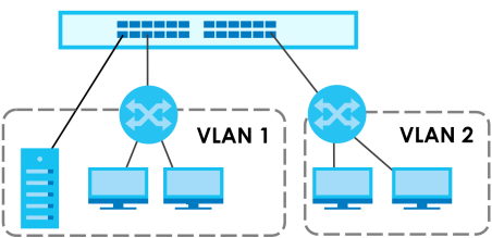
IEEE 802.1Q Tagged VLANs
A tagged VLAN uses an explicit tag (VLAN ID) in the MAC header to identify the VLAN membership of a frame across bridges – they are not confined to the switch on which they were created. The VLANs can be created statically by hand dynamically through GVRP. The VLAN ID associates a frame with a specific VLAN and provides the information that switches need to process the frame across the network. A tagged frame is 4 bytes longer than an untagged frame and contains 2 bytes of TPID (Tag Protocol Identifier, residing within the type or length field of the Ethernet frame) and 2 bytes of TCI (Tag Control Information, starts after the source address field of the Ethernet frame).
The CFI (Canonical Format Indicator) is a single-bit flag, always set to zero for Ethernet switches. If a frame received at an Ethernet port has a CFI set to 1, then that frame should not be forwarded as it is to an untagged port. The remaining twelve bits define the VLAN ID, giving a possible maximum number of 4,096 VLANs. Note that user priority and VLAN ID are independent of each other. A frame with VID (VLAN Identifier) of null (0) is called a priority frame, meaning that only the priority level is significant and the default VID of the ingress port is given as the VID of the frame. Of the 4,096 possible VIDs, a VID of 0 is used to identify priority frames and value 4095 (FFF) is reserved, so the maximum possible VLAN configurations are 4,094.
TPID 2 Bytes | User Priority 3 Bits | CFI 1 Bit | VLAN ID 12 bits |
Forwarding Tagged and Untagged Frames
Each port on the Switch is capable of passing tagged (T) or untagged (UT) frames. To forward a frame from an 802.1Q VLAN-aware switch to an 802.1Q VLAN-unaware switch, the Switch first decides where to forward the frame and then strips off the VLAN tag (VT). To forward a frame from an 802.1Q VLAN-unaware switch to an 802.1Q VLAN-aware switch, the Switch first decides where to forward the frame, and then inserts a VLAN tag (VT) reflecting the ingress port's default VID. The default PVID is VLAN 1 for all ports, but this can be changed.
VLAN Forwarding Frame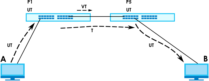
A broadcast frame (or a multicast frame for a multicast group that is known by the system) is duplicated only on ports that are members of the VID (except the ingress port itself), thus confining the broadcast to a specific domain.
Automatic VLAN Registration
GARP and GVRP are the protocols used to automatically register VLAN membership across switches.
GARP
GARP (Generic Attribute Registration Protocol) allows network switches to register and de-register attribute values with other GARP participants within a bridged LAN. GARP is a protocol that provides a generic mechanism for protocols that serve a more specific application, for example, GVRP.
GARP Timers
Switches join VLANs by making a declaration. A declaration is made by issuing a Join message using GARP. Declarations are withdrawn by issuing a Leave message. A Leave All message terminates all registrations. GARP timers set declaration timeout values.
GVRP
GVRP (GARP VLAN Registration Protocol) is a registration protocol that defines a way for switches to register necessary VLAN members on ports across the network. Enable this function to permit VLAN groups beyond the local Switch.
Please refer to the following table for common IEEE 802.1Q VLAN terminology.
VLAN Parameter | Term | Description |
|---|---|---|
VLAN Type | Permanent VLAN | This is a static VLAN created manually. |
Dynamic VLAN | This is a VLAN configured by a GVRP registration or de-registration process. | |
VLAN Administrative Control | Registration Fixed | Fixed registration ports are permanent VLAN members. |
Registration Forbidden | Ports with registration forbidden are forbidden to join the specified VLAN. | |
Normal Registration | Ports dynamically join a VLAN using GVRP. | |
VLAN Tag Control | Tagged | Ports belonging to the specified VLAN tag all outgoing frames transmitted. |
Untagged | Ports belonging to the specified VLAN do not tag all outgoing frames transmitted. | |
VLAN Port | Port VID | This is the VLAN ID assigned to untagged frames that this port received. |
Acceptable Frame Type | You may choose to accept both tagged and untagged incoming frames, just tagged incoming frames or just untagged incoming frames on a port. | |
Ingress filtering | If set, the Switch discards incoming frames for VLANs that do not have this port as a member. |
Port VLAN Trunking
Enable VLAN Trunking on a port to allow frames belonging to unknown VLAN groups to pass through that port. This is useful if you want to set up VLAN groups on end devices without having to configure the same VLAN groups on intermediary devices.
Refer to the following figure. Suppose you want to create VLAN groups 1 and 2 (V1 and V2) on switches A and B. Without VLAN Trunking, you must configure VLAN groups 1 and 2 on all intermediary switches C, D and E; otherwise they will drop frames with unknown VLAN group tags. However, with VLAN Trunking enabled on ports in each intermediary switch you only need to create VLAN groups in the end devices (A and B). C, D and E automatically allow frames with VLAN group tags 1 and 2 (VLAN groups that are unknown to those switches) to pass through their VLAN trunking ports.
Port VLAN Trunking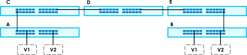
VLAN Status
Use this screen to view and search all static VLAN groups.
The following table describes the labels in this screen.
label | description |
|---|---|
VLAN Search by VID | Enter (an) existing VLAN ID numbers (use a comma (,) to separate individual VLANs or a hyphen (-) to indicate a range of VLANs. For example, “3,4” or “3-9”) and click Search to display only the specified VLANs in the list below. Leave this field blank and click Search to display all VLANs configured on the Switch. |
The Number of VLAN | This is the number of VLANs configured on the Switch. |
The Number of Search Results | This is the number of VLANs that match the searching criteria and display in the list below. This field displays only when you use the Search button to look for certain VLANs. |
Index | This is the VLAN index number. Click an index number to view more VLAN details. |
VID | This is the VLAN identification number that was configured in the corresponding VLAN configuration screen. |
Name | This fields shows the descriptive name of the VLAN. |
Tagged Port | This field shows the tagged ports that are participating in the VLAN. |
Untagged Port | This field shows the untagged ports that are participating in the VLAN. |
Elapsed Time | This field shows how long it has been since a normal VLAN was registered or a static VLAN was set up. |
Status | This field shows how this VLAN was added to the Switch. • Dynamic – using GVRP • Static – manually added as a normal VLAN • MVR – added through Multicast VLAN Registration (MVR) |
VLAN Details
Use this screen to view detailed port settings and status of the static VLAN group. Click an index number in the VLAN Status screen to display VLAN details.
The following table describes the labels in this screen.
label | description |
|---|---|
VID | This is the VLAN identification number that was configured in the corresponding VLAN configuration screen. |
Elapsed Time | This field shows how long it has been since a normal VLAN was registered or a static VLAN was set up. |
Status | This field shows how this VLAN was added to the Switch. • Dynamic – using GVRP • Static – manually added as a normal VLAN • MVR – added through Multicast VLAN Registration (MVR) |
Port Number | This section displays the ports that are participating in a VLAN. A tagged port is marked as T, an untagged port is marked as U and ports not participating in a VLAN are marked as “–“. |
Configure a Static VLAN
Use a static VLAN to decide whether an incoming frame on a port should be
• sent to a VLAN group as normal depending on its VLAN tag.
• sent to a group whether it has a VLAN tag or not.
• blocked from a VLAN group regardless of its VLAN tag.
You can also tag all outgoing frames (that were previously untagged) from a port with the specified VID.
Use this screen to view and configure a static VLAN for the Switch.
The following table describes the related labels in this screen.
label | Description |
|---|---|
VID | This field displays the ID number of the VLAN group. |
Active | This field indicates whether the VLAN settings are enabled or disabled. |
Name | This field displays the descriptive name for this VLAN group. |
Select an entry’s checkbox to select a specific entry. Otherwise, select the checkbox in the table heading row to select all entries. | |
Add/Edit | Click Add/Edit to add a new static VLAN or edit a selected one. |
Delete | Click Delete to remove the selected static VLAN. |
Add/Edit a Static VLAN
Use this screen to configure a static VLAN for the Switch. Click Add/Edit, or select an entry and click Add/Edit in the SWITCHING > VLAN > Static VLAN screen to display this screen.
The following table describes the related labels in this screen.
label | Description |
|---|---|
Active | Enable the switch button to activate the VLAN settings. |
Name | Enter a descriptive name for the VLAN group for identification purposes. This name consists of up to 64 printable ASCII characters. The string should not contain [ ? ], [ | ], [ ' ], [ " ], or [ , ]. |
VLAN Group ID | Enter the VLAN ID for this static entry; the valid range is between 1 and 4094. |
Port | The port number identifies the port you are configuring. |
* | Settings in this row apply to all ports. Use this row only if you want to make some settings the same for all ports. Use this row first to set the common settings and then make adjustments on a port-by-port basis. |
Control | Select Normal for the port to dynamically join this VLAN group. This is the default selection. Select Fixed for the port to be a permanent member of this VLAN group. Select Forbidden if you want to prohibit the port from joining this VLAN group. |
Tagging | Select Tx Tagging if you want outgoing traffic to contain this VLAN tag. Otherwise, to ensure that VLAN-unaware devices (such as computers and hubs) can receive frames properly, clear the Tx Tagging checkbox to set the Switch to remove VLAN tags before sending. |
Apply | Click Apply to save your changes to the Switch’s run-time memory. The Switch loses these changes if it is turned off or loses power, so use the Save link on the top navigation panel to save your changes to the non-volatile memory when you are done configuring. |
Clear | Click Clear to clear the fields to the factory defaults. |
Cancel | Click Cancel to not save the configuration you make and return to the last screen. |
VLAN Port Setup
Use this screen to configure the static VLAN (IEEE 802.1Q) settings on a port.
The following table describes the labels in this screen.
label | description |
|---|---|
Port | This field displays the port number. |
* | Settings in this row apply to all ports. Use this row only if you want to make some settings the same for all ports. Use this row first to set the common settings and then make adjustments on a port-by-port basis. |
Ingress Check | If this checkbox is selected, the Switch discards incoming frames on a port for VLANs that do not include this port in its member set. Clear this checkbox to disable ingress filtering. |
PVID | A PVID (Port VLAN ID) is a tag that adds to incoming untagged frames received on a port so that the frames are forwarded to the VLAN group that the tag defines. Enter a number between 1and 4094 as the port VLAN ID. |
Acceptable Frame Type | Specify the type of frames allowed on a port. Choices are All, Tag Only and Untag Only. Select All from the drop-down list box to accept all untagged or tagged frames on this port. This is the default setting. Select Tag Only to accept only tagged frames on this port. All untagged frames will be dropped. Select Untag Only to accept only untagged frames on this port. All tagged frames will be dropped. |
VLAN Trunking | Enable VLAN Trunking on ports connected to other switches or routers (but not ports directly connected to end users) to allow frames belonging to unknown VLAN groups to pass through the Switch. |
Isolation | Select this to allows this port to communicate only with the CPU management port and the ports on which the isolation feature is NOT enabled. |
Apply | Click Apply to save your changes to the Switch’s run-time memory. The Switch loses these changes if it is turned off or loses power, so use the Save link on the top navigation panel to save your changes to the non-volatile memory when you are done configuring. |
Cancel | Click Cancel to begin configuring this screen afresh. |
Port-Based VLAN Setup
Port-based VLANs are VLANs where the packet forwarding decision is based on the destination MAC address and its associated port.
Port-based VLANs require allowed outgoing ports to be defined for each port. Therefore, if you wish to allow two subscriber ports to talk to each other, for example, between conference rooms in a hotel, you must define the egress (an egress port is an outgoing port, that is, a port through which a data packet leaves) for both ports.
Port-based VLANs are specific only to the Switch on which they were created.
The CPU management port forms a VLAN with all Ethernet ports.
Configure a Port-Based VLAN
The following table describes the labels in this screen.
label | Description |
|---|---|
Setting Wizard | Choose Current configuration to display the Switch’s current port-based VLAN configuration. Choose All connected or Port isolation wizard to quickly set up a port-based VLAN according to the below descriptions. All connected means all ports can communicate with each other, that is, there are no virtual LANs. All incoming and outgoing ports are selected. This option is the most flexible but also the least secure. Port isolation means that each port can only communicate with the CPU management port and cannot communicate with each other. All incoming ports are selected while only the CPU outgoing port is selected. This option is the most limiting but also the most secure. After selecting the setting wizard, you can customize the port settings. Click on the ports to add or delete incoming or outgoing ports. The configuration will be saved only after you click Apply at the bottom of the screen. |
Incoming | These are the ingress ports; an ingress port is an incoming port, that is, a port through which a data packet enters. If you wish to allow two subscriber ports to talk to each other, you must define the ingress port for both ports. The numbers in the top row denote the incoming port for the corresponding port listed on the left (its outgoing port). CPU refers to the Switch management port. By default it forms a VLAN with all Ethernet ports. If it does not form a VLAN with a particular port then the Switch cannot be managed from that port. |
Outgoing | These are the egress ports; an egress port is an outgoing port, that is, a port through which a data packet leaves. If you wish to allow two subscriber ports to talk to each other, you must define the egress port for both ports. CPU refers to the Switch management port. By default it forms a VLAN with all Ethernet ports. If it does not form a VLAN with a particular port then the Switch cannot be managed from that port. |
Apply | Click Apply to save your changes to the Switch’s run-time memory. The Switch loses these changes if it is turned off or loses power, so use the Save link on the top navigation panel to save your changes to the non-volatile memory when you are done configuring. |
Cancel | Click Cancel to begin configuring this screen afresh. |