SYSTEM
The following sections introduces the SYSTEM screens.
What You Can Do
• Use the Cloud Management screen (Cloud Management) to view NCC Connection status and enable/disable NCC Discovery.
• Use the General Setup screen (General Setup) to configure general settings such as the system name and time.
• Use the IP Setup screen (IP Setup) to configure the default gateway device, the default domain name server and add IP domains.
• Use the Logins screen (Logins) to change the system password, configure passwords for up to four users and set their privilege level.
• Use the SNMP screen (Configure SNMP) to configure your SNMP (Simple Network Management Protocol) settings.
• Use the SNMP User screen (SNMP User) to create SNMP users for authentication with managers using SNMP v3 and associate them to SNMP groups.
• Use the SNMP Trap Group screen (SNMP Trap Group) to specify the types of SNMP traps that should be sent to each SNMP manager.
• Use the SNMP Trap Port screen (SNMP Traps on a Port) to set whether a trap received on the ports would be sent to the SNMP manager.
Cloud Management
The Zyxel Nebula Control Center (NCC) is a cloud-based network management system that allows you to remotely manage and monitor Zyxel Nebula APs, Ethernet switches, security gateways, security routers, mobile routers, and accessories.
The Switch is managed and provisioned automatically by the NCC (Nebula Control Center) when:
• It is connected to the Internet.
• The Nebula Control Center Discovery feature is enabled.
• It has been registered in the NCC.
The following table describes the labels in this screen.
label | description |
|---|---|
Nebula Control Center (NCC) Discovery | Enable the switch button to turn on Nebula Control Center (NCC) discovery on the Switch. This field displays: • The Switch Internet connection status. • The connection status between the Switch and NCC. • The Switch registration status on NCC. Mouse over the circles to display detailed information. To pass your Switch management to NCC, first make sure your Switch is connected to the Internet. Then go to NCC and register your Switch. 1. Internet Green – The Switch is connected to the Internet. Orange – The Switch is not connected to the Internet. 2. Nebula Green – The Switch is connected to NCC. Orange – The Switch is not connected to NCC. 3. Registration Green – The Switch is registered on NCC. Gray – The Switch is not registered on NCC. |
Connection Status | This table displays the NCC connection status information. Use the status logs in the Internet, Nebula, and Registration fields for connection troubleshooting. |
Enable Nebula Control Center (NCC) Discovery to turn on NCC discovery on the Switch. If the Switch has Internet access and has been registered in the NCC, it will go into cloud management mode.
Disable Nebula Control Center (NCC) Discovery to turn off NCC discovery on the Switch. The Switch will NOT discover the NCC and remain in standalone mode.
This screen has a QR code containing the Switch’s serial number and Registration MAC address for handy NCC registration of the Switch using the Nebula Mobile app. First, download the app from the Google Play store for Android devices or the App Store for iOS devices and create an organization and site. Open the Nebula Mobile app and follow the wizard to scan the Register Device QR code to register the Switch on NCC.
General Setup
Use this screen to configure general settings such as the system name and time.
The following table describes the labels in this screen.
label | description |
|---|---|
System Name | Choose a descriptive name for identification purposes. This name consists of up to 64 printable ASCII characters; spaces are allowed. |
Location | Enter the geographic location of your Switch. You can use up to 128 printable ASCII characters; spaces are allowed. |
Contact Person's Name | Enter the name of the person in charge of this Switch. You can use up to 32 printable ASCII characters; spaces are allowed. |
Use Time Server when Bootup | Enter the time service protocol that your time server uses. Not all time servers support all protocols, so you may have to use trial and error to find a protocol that works. The main differences between them are the time format. When you select the Daytime (RFC-867) format, the Switch displays the day, month, year and time with no time zone adjustment. When you use this format it is recommended that you use a Daytime timeserver within your geographical time zone. Time (RFC-868) format displays a 4-byte integer giving the total number of seconds since 1970/1/1 at 00:00:00. NTP (RFC-1305) is similar to Time (RFC-868). None is the default value. Enter the time manually. Each time you turn on the Switch, the time and date will be reset to 2022-01-01 00:00:00. |
Time Server 1 / 2 / 3 | Enter the IPv4 / IPv6 address or domain name of your time server. The Switch searches for the first, then the second, then the third time server for around 60 seconds. |
Time Server Sync Interval | Enter the period in minutes between each time server synchronization. The Switch checks the time server after every synchronization interval. |
Current Time | This field displays the time you open this menu (or refresh the menu). |
New Time (hh:mm:ss) | Enter the new time in hour, minute and second format. The new time then appears in the Current Time field after you click Apply. |
Current Date | This field displays the date you open this menu. |
New Date (yyyy-mm-dd) | Enter the new date in year, month and day format. The new date then appears in the Current Date field after you click Apply. |
Time Zone | Select the time difference between UTC (Universal Time Coordinated, formerly known as GMT, Greenwich Mean Time) and your time zone from the drop-down list box. |
Daylight Saving Time | Daylight saving is a period from late spring to early fall when many countries set their clocks ahead of normal local time by one hour to give more daytime light in the evening. Enable the switch button if you use Daylight Saving Time. |
Start Date | Configure the day and time when Daylight Saving Time starts if you selected Daylight Saving Time. The time is displayed in the 24 hour format. Here are a couple of examples: Daylight Saving Time starts in most parts of the United States on the second Sunday of March. Each time zone in the United States starts using Daylight Saving Time at 2 A.M. local time. So in the United States you would select Second, Sunday, March and 2:00. Daylight Saving Time starts in the European Union on the last Sunday of March. All of the time zones in the European Union start using Daylight Saving Time at the same moment (1 A.M. GMT or UTC). So in the European Union you would select Last, Sunday, March and the last field depends on your time zone. In Germany for instance, you would select 2:00 because Germany's time zone is one hour ahead of GMT or UTC (GMT+1). |
End Date | Configure the day and time when Daylight Saving Time ends if you selected Daylight Saving Time. The time field uses the 24 hour format. Here are a couple of examples: Daylight Saving Time ends in the United States on the first Sunday of November. Each time zone in the United States stops using Daylight Saving Time at 2 A.M. local time. So in the United States you would select First, Sunday, November and 2:00. Daylight Saving Time ends in the European Union on the last Sunday of October. All of the time zones in the European Union stop using Daylight Saving Time at the same moment (1 A.M. GMT or UTC). So in the European Union you would select Last, Sunday, October and the last field depends on your time zone. In Germany for instance, you would select 2:00 because Germany's time zone is one hour ahead of GMT or UTC (GMT+1). |
Apply | Click Apply to save your changes to the Switch’s run-time memory. The Switch loses these changes if it is turned off or loses power, so use the Save link on the top navigation panel to save your changes to the non-volatile memory when you are done configuring. |
Cancel | Click Cancel to begin configuring this screen afresh. |
IP Setup
Use the IP Setup screen to configure the default gateway device, the default domain name server and add IP domains.
The following table describes the labels in this screen.
label | description |
|---|---|
Domain Name Server | |
Default Gateway | Enter the IP address of the default outgoing gateway in dotted decimal notation, for example 192.168.1.254. |
Domain Name Server 1/2 | Enter a domain name server IPv4 address in order to be able to use a domain name instead of an IP address. |
Apply | Click Apply to save your changes to the Switch’s run-time memory. The Switch loses these changes if it is turned off or loses power, so use the Save link on the top navigation panel to save your changes to the non-volatile memory when you are done configuring. |
Cancel | Click Cancel to reset the fields to your previous configuration. |
Default Management IP Address Use these fields to create or edit IP routing domains on the Switch. | |
DHCP Client | Select this option if you have a DHCP server that can assign the Switch an IP address, subnet mask, a default gateway IP address and a domain name server IP address automatically. |
Static IP Address | Select this option if you do not have a DHCP server or if you wish to assign static IP address information to the Switch. You need to fill in the following fields when you select this option. |
Select an entry’s checkbox to select a specific entry. Otherwise, select the checkbox in the table heading row to select all entries. | |
Index | This is the IP routing domain entry number. |
IP Address | This is the IP address of the Switch in an IP routing domain. |
IP Subnet Mask | This is the IP subnet mask of an IP routing domain in dotted decimal notation, for example, 255.255.252.0. |
Default Gateway | Enter the IP address of the default outgoing gateway in dotted decimal notation, for example 172.21.43.254. |
VID | Enter the VLAN identification number to which an IP routing domain belongs. |
Apply | Click Apply to save your changes to the Switch’s run-time memory. The Switch loses these changes if it is turned off or loses power, so use the Save link on the top navigation panel to save your changes to the non-volatile memory when you are done configuring. |
Cancel | Click Cancel to reset the fields to your previous configuration. |
Management IP Address | |
Select an entry’s checkbox to select a specific entry. Otherwise, select the checkbox in the table heading row to select all entries. | |
Index | This field displays the index number of an entry. |
IP Address | This field displays IP address of the Switch in the IP domain. |
IP Subnet Mask | This field displays the subnet mask of the Switch in the IP domain. |
VID | This field displays the VLAN identification number of the IP domain on the Switch. |
Default Gateway | This field displays the IP address of the default outgoing gateway in dotted decimal notation. |
Add/Edit | Click Add/Edit to add a new management port setting or edit a selected one. |
Delete | Click Delete to remove the selected entry from the summary table. |
Add/Edit IP Interfaces
Use this screen to add or edit IP interfaces. Click Add/Edit, or select an entry and click Add/Edit in the SYSTEM > IP Setup > IP Setup screen to display this screen.
The following table describes the labels in this screen.
label | description |
|---|---|
IP Address | Enter the IP address of your Switch in dotted decimal notation, for example, 192.168.1.1. This is the IP address of the Switch in an IP routing domain. |
IP Subnet Mask | Enter the IP subnet mask of an IP routing domain in dotted decimal notation, for example, 255.255.255.0. |
Default Gateway | Enter the IP address of the default outgoing gateway in dotted decimal notation, for example 172.21.43.254. |
VID | Enter the VLAN identification number to which an IP routing domain belongs. |
Apply | Click Apply to save your changes to the Switch’s run-time memory. The Switch loses these changes if it is turned off or loses power, so use the Save link on the top navigation panel to save your changes to the non-volatile memory when you are done configuring. |
Clear | Click Clear to clear the fields to the factory defaults. |
Cancel | Click Cancel to not save the configuration you make and return to the last screen. |
Logins
Up to five people (one administrator and four non-administrators) may access the Switch through Web Configurator at any one time.
• An administrator is someone who can both view and configure Switch changes. The default user name for the Administrator is admin. The default administrator password is 1234.
• A non-administrator (user name is something other than admin) is someone who can view and/or configure Switch settings. The configuration right varies depending on the user’s privilege level.
The following table describes the labels in this screen.
LABEL | Description |
|---|---|
Administrator This is the default administrator account with the “admin” user name. You cannot change the default administrator user name. | |
User Name | Change the default “admin” system user name (up to 32 printable ASCII characters except [ ? ], [ | ], [ ' ], [ " ], [ space ], [ , ], or [ : ]. |
Old Password | Enter the existing system password (1234 is the default password when shipped). |
New Password | Enter your new system password. The password rule when Password Complexity is disabled in SECURITY > Access Control > Account Security > Account Security is: • 4 to 32 characters in length The password rule when Password Complexity is enabled are: • 9 to 32 characters in length • Include at least three of these: numbers, uppercase letters, lowercase letters, and special characters (for example, ‘Ea5yPas5W0rd’) • Cannot match your login username • Cannot use the same character (case insensitive) or number three or more times in a row (for example, ‘777’, ‘AaA’) • Cannot use four or more sequential keyboard characters (case insensitive) or numbers (for example, ‘qWer’, ‘1234’), and • Cannot use the present password again. |
Retype to confirm | Re-enter your new system password for confirmation. |
Edit Logins You may configure passwords for up to four users. These users can have read-only or read/write access. You can give users higher privileges through the Web Configurator or the CLI. For more information on assigning privileges through the CLI see the Ethernet Switch CLI Reference Guide. | |
Login | This is the index of an user account. |
User Name | Set a user name (up to 32 printable ASCII characters except [ ? ], [ | ], [ ' ], [ " ], or [ , ]). |
Password | Enter your new system password. The password rule when Password Complexity is disabled in SECURITY > Access Control > Account Security > Account Security is: • 4 to 32 characters in length The password rule when Password Complexity is enabled are: • 9 to 32 characters in length • Include at least three of these: numbers, uppercase letters, lowercase letters, and special characters (for example, ‘Ea5yPas5W0rd’) • Cannot match your login username • Cannot use the same character (case insensitive) or number three or more times in a row (for example, ‘777’, ‘AaA’) • Cannot use four or more sequential keyboard characters (case insensitive) or numbers (for example, ‘qWer’, ‘1234’), and • Cannot use the present password again. |
Retype to confirm | Retype your new system password for confirmation. |
Privilege | Enter the privilege level for this user. At the time of writing, users may have a privilege level of 0, 3, 13, or 14 representing different configuration rights as shown below. • 0 – Display basic system information. • 3 – Display configuration or status. • 13 – Configure features except for login accounts, SNMP user accounts, the authentication method sequence and authorization settings, multiple logins, administrator and enable passwords, and configuration information display. • 14 – Configure login accounts, SNMP user accounts, the authentication method sequence and authorization settings, multiple logins, and administrator and enable passwords, and display configuration information. Users can run command lines if the session’s privilege level is greater than or equal to the command’s privilege level. The session privilege initially comes from the privilege of the login account. For example, if the user has a privilege of 5, he or she can run commands that requires privilege level of 5 or less but not more. |
Apply | Click Apply to save your changes to the Switch’s run-time memory. The Switch loses these changes if it is turned off or loses power, so use the Save link on the top navigation panel to save your changes to the non-volatile memory when you are done configuring. |
Cancel | Click Cancel to begin configuring this screen afresh. |
Configure SNMP
Use this screen to configure your SNMP settings. Simple Network Management Protocol (SNMP) is an application layer protocol used to manage and monitor TCP/IP-based devices. SNMP is used to exchange management information between the network management system (NMS) and a network element (NE). A manager station can manage and monitor the Switch through the network through SNMP version 1 (SNMPv1), SNMP version 2c or SNMP version 3. The next figure illustrates an SNMP management operation. SNMP is only available if TCP/IP is configured.
SNMP Management Model 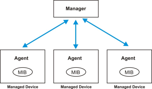
An SNMP managed network consists of two main components: agents and a manager.
An agent is a management software module that resides in a managed Switch (the Switch). An agent translates the local management information from the managed Switch into a form compatible with SNMP. The manager is the console through which network administrators perform network management functions. It executes applications that control and monitor managed devices.
The managed devices contain object variables or managed objects that define each piece of information to be collected about a Switch. Examples of variables include number of packets received, node port status and so on. A Management Information Base (MIB) is a collection of managed objects. SNMP allows a manager and agents to communicate for the purpose of accessing these objects.
SNMP itself is a simple request or response protocol based on the manager or agent model. The manager issues a request and the agent returns responses using the following protocol operations:
LABEL | DESCRIPTION |
|---|---|
Get | Allows the manager to retrieve an object variable from the agent. |
GetNext | Allows the manager to retrieve the next object variable from a table or list within an agent. In SNMPv1, when a manager wants to retrieve all elements of a table from an agent, it initiates a Get operation, followed by a series of GetNext operations. |
Set | Allows the manager to set values for object variables within an agent. |
Trap | Used by the agent to inform the manager of some events. |
SNMP v3 and Security
SNMP v3 enhances security for SNMP management. SNMP managers can be required to authenticate with agents before conducting SNMP management sessions.
Security can be further enhanced by encrypting the SNMP messages sent from the managers. Encryption protects the contents of the SNMP messages. When the contents of the SNMP messages are encrypted, only the intended recipients can read them.
The following table describes the labels in this screen.
LABEL | Description |
|---|---|
General Setting Use this section to specify the SNMP version and community (password) values. | |
Version | Select the SNMP version for the Switch. The SNMP version on the Switch must match the version on the SNMP manager. Choose SNMP version 2c (v2c), SNMP version 3 (v3) or both (v3v2c). SNMP version 2c is backwards compatible with SNMP version 1. |
Get Community | Enter the Get Community string, which is the password for the incoming Get- and GetNext- requests from the management station. The Get Community string is only used by SNMP managers using SNMP version 2c or lower. |
Set Community | Enter the Set Community string, which is the password for incoming Set- requests from the management station. The Set Community string is only used by SNMP managers using SNMP version 2c or lower. |
Trap Community | Enter the Trap Community string, which is the password sent with each trap to the SNMP manager. The Trap Community string is only used by SNMP managers using SNMP version 2c or lower. |
Trap Destination Use this section to configure where to send SNMP traps from the Switch. | |
Index | This is the index of a trap destination. |
Version | Specify the version of the SNMP trap messages. |
IP | Enter the IP addresses of up to four managers to send your SNMP traps to. |
Port | Enter the port number upon which the manager listens for SNMP traps. |
Username | Enter the user name to be sent to the SNMP manager along with the SNMP v3 trap. This user name must match an existing account on the Switch (configured in the SYSTEM > SNMP > SNMP User screen). |
Apply | Click Apply to save your changes to the Switch’s run-time memory. The Switch loses these changes if it is turned off or loses power, so use the Save link on the top navigation panel to save your changes to the non-volatile memory when you are done configuring. |
Cancel | Click Cancel to begin configuring this screen afresh. |
SNMP User
Use this screen to create SNMP users for authentication with managers using SNMP v3 and associate them to SNMP groups. An SNMP user is an SNMP manager.
The following table describes the labels in this screen.
LABEL | Description |
|---|---|
Select an entry’s checkbox to select a specific entry. Otherwise, select the checkbox in the table heading row to select all entries. | |
Index | This is a read-only number identifying a login account on the Switch. |
Username | This field displays the user name of a login account on the Switch. |
Security Level | This field displays whether you want to implement authentication and/or encryption for SNMP communication with this user. |
Authentication | This field displays the authentication algorithm used for SNMP communication with this user. |
Privacy | This field displays the encryption method used for SNMP communication with this user. |
Group | This field displays the SNMP group to which this user belongs. |
Add/Edit | Click Add/Edit to add a new entry or edit a selected one. |
Delete | Click Delete to remove the selected entries. |
Add/Edit SNMP User
Use this screen to create SNMP users for authentication with managers using SNMP v3 and associate them to SNMP groups. An SNMP user is an SNMP manager. Click Add/Edit, or select an entry and click Add/Edit in the SYSTEM > SNMP > SNMP User screen to view this screen.
The following table describes the labels in this screen.
LABEL | Description |
|---|---|
Username | Specify the user name (up to 32 printable ASCII characters) of a login account on the Switch. The string should not contain [ ? ], [ | ], [ ' ], [ " ], [ , ], [ : ], or space. |
Security Level | Select whether you want to implement authentication and/or encryption for SNMP communication from this user. Choose: • no auth – to use the user name as the password string to send to the SNMP manager. This is equivalent to the Get, Set and Trap Community in SNMP v2c. This is the lowest security level. • auth – to implement an authentication algorithm for SNMP messages sent by this user. • priv – to implement authentication and encryption for SNMP messages sent by this user. This is the highest security level. |
Authentication | Select an authentication algorithm. MD5 (Message Digest 5) and SHA (Secure Hash Algorithm) are hash algorithms used to authenticate SNMP data. SHA authentication is generally considered stronger than MD5, but is slower. |
Password | When you select no auth in Security Level, enter the password of up to 32 printable ASCII characters (except [ ? ], [ | ], [ ' ], [ " ], [ space ], [ , ], [ [ ] , or [ ] ]). When you select auth or priv in Security Level, the password rule when Password Complexity is disabled in SECURITY > Access Control > Account Security > Account Security for SNMP user authentication is: • 4 to 32 characters in length The password rule when Password Complexity is enabled are: • 9 to 32 characters in length • Include at least three of these: numbers, uppercase letters, lowercase letters, and special characters (for example, ‘Ea5yPas5W0rd’) • Cannot match your login username • Cannot use the same character (case insensitive) or number three or more times in a row (for example, ‘777’, ‘AaA’) • Cannot use four or more sequential keyboard characters (case insensitive) or numbers (for example, ‘qWer’, ‘1234’), and • Cannot use the present password again. |
Privacy | Specify the encryption method for SNMP communication from this user. You can choose one of the following: • DES – Data Encryption Standard is a widely used (but breakable) method of data encryption. It applies a 56-bit key to each 64-bit block of data. • AES – Advanced Encryption Standard is another method for data encryption that also uses a secret key. AES applies a 128-bit key to 128-bit blocks of data. |
Password | When you select no auth or auth in Security Level, enter the password of up to 32 printable ASCII characters (except [ ? ], [ | ], [ ' ], [ " ], [ space ], [ , ], [ [ ] , or [ ] ]). When you select priv in Security Level, the password rule when Password Complexity is disabled in SECURITY > Access Control > Account Security > Account Security for encrypting SNMP packets is: • 4 to 32 characters in length The password rule when Password Complexity is enabled are: • 9 to 32 characters in length • Include at least three of these: numbers, uppercase letters, lowercase letters, and special characters (for example, ‘Ea5yPas5W0rd’) • Cannot match your login username • Cannot use the same character (case insensitive) or number three or more times in a row (for example, ‘777’, ‘AaA’) • Cannot use four or more sequential keyboard characters (case insensitive) or numbers (for example, ‘qWer’, ‘1234’), and • Cannot use the present password again. |
Group | SNMP v3 adopts the concept of View-based Access Control Model (VACM) group. SNMP managers in one group are assigned common access rights to MIBs. Specify in which SNMP group this user is. admin – Members of this group can perform all types of system configuration, including the management of administrator accounts. read-write – Members of this group have read and write rights, meaning that the user can create and edit the MIBs on the Switch, except the user account and AAA configuration. read-only – Members of this group have read rights only, meaning the user can collect information from the Switch. |
Apply | Click Apply to save your changes to the Switch’s run-time memory. The Switch loses these changes if it is turned off or loses power, so use the Save link on the top navigation panel to save your changes to the non-volatile memory when you are done configuring. |
Clear | Click Clear to clear the fields to the factory defaults. |
Cancel | Click Cancel to not save the configuration you make and return to the last screen. |
SNMP Trap Group
Use this screen to specify the types of SNMP traps that should be sent to each SNMP manager.
The following table describes the labels in this screen.
LABEL | Description |
|---|---|
Trap Destination IP | Select one of your configured trap destination IP addresses. These are the IP addresses of the SNMP managers. You must first configure a trap destination IP address in the SYSTEM > SNMP > SNMP screen. Use the rest of the screen to select which traps the Switch sends to that SNMP manager. |
Select the individual SNMP traps that the Switch is to send to the SNMP station. The traps are grouped by category. Selecting a category in the heading row automatically selects all of the SNMP traps under that category. Clear the checkboxes for individual traps that you do not want the Switch to send to the SNMP station. Clearing a category’s checkbox automatically clears all of the category’s trap checkboxes (the Switch only sends traps from selected categories). | |
Apply | Click Apply to save your changes to the Switch’s run-time memory. The Switch loses these changes if it is turned off or loses power, so use the Save link on the top navigation panel to save your changes to the non-volatile memory when you are done configuring. |
Cancel | Click Cancel to begin configuring this screen afresh. |
SNMP Traps on a Port
Use this screen to set whether a trap received on the ports would be sent to the SNMP manager.
The following table describes the labels in this screen.
LABEL | Description |
|---|---|
Options | Select the trap type you want to configure here. |
Port | This field displays a port number. |
* | Settings in this row apply to all ports. Use this row only if you want to make some of the settings the same for all ports. Use this row first to set the common settings and then make adjustments on a port-by-port basis. Changes in this row are copied to all the ports as soon as you make them. |
Active | Select this checkbox to enable the trap type of SNMP traps on this port. The Switch sends the related traps received on this port to the SNMP manager. Clear this checkbox to disable the sending of SNMP traps on this port. |
Apply | Click Apply to save your changes to the Switch’s run-time memory. The Switch loses these changes if it is turned off or loses power, so use the Save link on the top navigation panel to save your changes to the non-volatile memory when you are done configuring. |
Cancel | Click Cancel to begin configuring this screen afresh. |