Web Configurator
System Login
1 Start your web browser.
2 The Switch is a DHCP client by default. Type “https://DHCP-assigned IP” in the Location or Address field. Press [ENTER].
If the Switch is not connected to a DHCP server, type “https://” and the static IP address of the Switch (for example, the default management IP address is 192.168.1.1 through an in-band port) in the Location or Address field. Press [ENTER]. Your computer must be in the same subnet in order to access this website address.
Also, you can use the ZON Utility to check your Switch’s IP address.
3 If a “Your connection is not private” screen appears, click Advanced and Proceed to DHCP-assigned IP (unsafe) to go to the Login screen. This screen appears as the Zyxel Device uses a certificate for the HTTPS connection. See Certificates for information on using an HTTPS certificate verified by a third party to create secure HTTPS connections between your computer and the Switch.
The Login screen appears.
4 In Standalone mode, click the Visit Nebula button if you want to open the Zyxel Nebula Control Center (NCC) login page in a new tab or window. In Cloud mode, click the Go Now button. The NCC is a cloud-based network management system that allows you to remotely manage and monitor the Switch. See Mode Changing for information on changing your Switch to Nebula Cloud management.
5 Alternatively, click Login to log into the Web Configurator to manage the Switch directly.
In Standalone mode, the default user name is admin and associated default password is 1234.
In Cloud mode, use the Local credentials: password to login. The Local credentials: Password can be found in Site-wide > Configure > Site settings > Device configuration in the NCC portal. See the NCC User’s Guide for more information.
In Standalone mode, the change password screen appears the first time you log in using the default password.
4 to 32 characters in length
[ ? ], [ | ], [ ' ], [ " ], [ , ], [ [ ], [ ] ] and space are not allowed
6 After setting the new password, close and restart your web browser. Enter the ‘https://DHCP-assigned IP’ in the URL field and press [ENTER]. When the login screen appears, enter the user name (default: ‘admin’) and new password.
When in Standalone mode, the Select Mode screen appears.
7 Select the Web Configurator in Standard Mode that has a complete set of configuration for network installation. Or select the Web Configurator in Networked AV Mode that has a set of menus specifically designed to simplify configuration and management of the Switch for AVoIP (Audio-Video over Internet Protocol) application.
8 The Setup Wizard screen will appear after selecting the Networked AV Mode. You can use the Setup Wizard screen to configure the Switch’s Networked AV mode’s basic or advanced settings (see Networked AV Mode Wizard for details).
• Use the Basic Settings to configure networked AV operation on management VLAN. Such as the Switches’ IP address, DNS server, system password, SNMP community, accept or skip the default Networked AV mode settings, and view a summary of the basic settings.
• Use the Advanced Settings for networks that wants to separate networked AV VLAN from management VLAN, specify which ports connect to AVoIP application, and for setting link aggregation across switches.
Once you click the Finish button, the settings configured in the Setup Wizard screen will overwrite the existing settings.
Otherwise, click the Exit button. You can select the Ignore this wizard next time checkbox and click Apply & Save if you do not want the Setup Wizard screen to appear the next time you log in. If you want to open the Setup Wizard screen later, click the Wizard icon in the upper right hand corner of the Web Configurator.
Networked AV Mode Wizard
The Setup Wizard can be accessed using the following methods:
• When the Switch is in its factory-default state, selecting Networked AV mode will automatically access the Setup Wizard.
• When in Networked AV mode, click the Wizard link to access the Setup Wizard.
Wizard Link in Networked AV Mode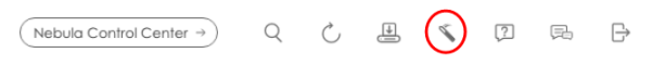
The Setup Wizard contains the following parts:
• Use the Basic Settings when networked AV service runs on management VLAN, using the combo/fiber port for inter-switch connection.
• Use the Advanced Settings when you need to specify the VLAN for networked AV service and configure the port’s role manually.
Basic Settings
In Basic Settings, you can set up IP or DNS, set up your password, SNMP community, accept or skip the default Networked AV mode settings, and view finished results.
In order to set up your IP or DNS, please do the following. Click Wizard > Basic Settings > Next > Step 1 IP to access this screen.
Each field is described in the following table.
Label | Description |
|---|---|
Host Name | This field displays a host name. |
IP Interface | Select DHCP Client if the Switch is connected to a router with the DHCP server enabled. You then need to check the router for the IP address assigned to the Switch in order to access the Switch’s Web Configurator again. Select Static IP Interface when the Switch is NOT connected to a router or you want to assign it a fixed IP address. |
VID | This field displays the VLAN ID. |
IP Address | The Switch needs an IP address for it to be managed over the network. |
IP Subnet Mask | The subnet mask specifies the network number portion of an IP address. |
Default Gateway | Type the IP address of the default outgoing gateway in dotted decimal notation, for example 192.168.1.254. |
DNS Server | DNS (Domain Name System) is for mapping a domain name to its corresponding IP address and vice versa. Enter a domain name server IP address in order to be able to use a domain name instead of an IP address. |
Next | Click Next to show the next screen. |
Cancel | Click Cancel to exit this screen without saving. |
After clicking Next, the Password screen appears.
Each field is described in the following table.
Label | Description |
|---|---|
Administrator's Password | |
Current password | Enter the existing system password (1234 is the default password when shipped). |
New Password | Enter your new system password. The password rule when Password Complexity is disabled in SECURITY > Access Control > Account Security > Account Security is: • 4 to 32 characters in length The password rule when Password Complexity is enabled are: • 9 to 32 characters in length • Include at least three of these: numbers, uppercase letters, lowercase letters, and special characters (for example, ‘Ea5yPas5W0rd’) • Cannot match your login username • Cannot use the same character (case insensitive) or number three or more times in a row (for example, ‘777’, ‘AaA’) • Cannot use four or more sequential keyboard characters (case insensitive) or numbers (for example, ‘qWer’, ‘1234’), and • Cannot use the present password again. |
Confirm password | Re-enter your new system password for confirmation. |
SNMP | |
SNMP | Select Enabled to let the Switch act as an SNMP agent, which allows a manager station to manage and monitor the Switch through the network. Select Disabled to turn this feature off. |
Version | Select the SNMP version for the Switch. The SNMP version on the Switch must match the version on the SNMP manager. Choose SNMP version 2c (v2c), SNMP version 3 (v3) or both (v3v2c). |
Get Community | Enter the Get Community string, which is the password for the incoming Get- and GetNextrequests from the management station. The Get Community string is only used by SNMP managers using SNMP version 2c or lower. |
Set Community | Enter the Set Community string, which is the password for the incoming Set- requests from the management station. The Set Community string is only used by SNMP managers using SNMP version 2c or lower. |
Trap Community | Enter the Trap Community string, which is the password sent with each trap to the SNMP manager. The Trap Community string is only used by SNMP managers using SNMP version 2c or lower. |
Previous | Click Previous to show the previous screen. |
Next | Click Next to show the next screen. |
Cancel | Click Cancel to exit this screen without saving. |
After clicking Next, the Networked AV screen appears.
Each field is described in the following table.
Label | Description |
|---|---|
Skip Networked AV Mode Settings | Click this option to avoid using the basic default AVoIP settings. The default AVoIP settings can be seen in Step 4 Summary under Networked AV – Basic Settings. Otherwise, clear the checkbox and follow the diagram for connecting RJ45 ports to audio and video equipment. The Inter-switch Connection is for connecting to another switch. |
Previous | Click Previous to show the previous screen. |
Next | Click Next to show the next screen. |
Cancel | Click Cancel to exit this screen without saving. |
After clicking Next, the Summary screen appears.
Each field is described in the following table.
Label | Description |
|---|---|
Setup IP | |
Host Name | This field displays a host name. |
IP Interface | This field displays whether the WAN interface is using a DHCP IP address or a static IP address. |
VID | This field displays the VLAN ID. |
IP Address | This field displays the Switch’s IP address for it to be managed over the network. |
IP Subnet Mask | This field displays the subnet mask that specifies the network number portion of an IP address. |
Default Gateway | This field displays the IP address of the default outgoing gateway in dotted decimal notation, for example 192.168.1.254. |
DNS Server | This field displays the DNS (Domain Name System) for mapping a domain name to its corresponding IP address and so forth. |
Change administrator's password and activate SNMP | |
New Password | This field displays asterisks when a new password has been created. |
SNMP | This field displays whether the Switch acts as an SNMP agent. |
Version | This field displays the SNMP version for the Switch. |
Get Community | This field displays the Get Community string. |
Set Community | This field displays the Set Community string. |
Trap Community | This field displays the Trap Community string. |
Networked AV – Basic Settings | |
Networked AV VLAN | This field displays the VLAN ID for the AVoIP network. |
Networked AV VLAN IP | This field displays the Switch’s IP address for it to be managed over the AVoIP network. |
IGMP Snooping | This field displays Active when IGMP Snooping is enabled to forward group multicast traffic only to ports that are members of that group. Otherwise, it displays Inactive. |
IGMP Snooping Querier | This field displays Active when the Switch is allowed to send IGMP General Query messages to the VLANs with the multicast hosts attached. Otherwise, it displays Inactive. |
Unknown Multicast Frame | This field displays the action to perform when the Switch receives an unknown multicast frame. It displays Drop when the frames are discarded. It displays Flooding when the frames are sent to all ports. |
Transmitter/Receiver Connected Port | This field shows the Switch’s port numbers for connection to networked audio and video equipment. |
Inter-switch Connected Port | This field shows the Switch’s port numbers for connection to another switch. |
Diffserv | This field displays Active. This means that IEEE 802.1p priority mapping in Quality of Service (QoS) is applied on the selected ports on the Switch. See Differentiated Services for more information on QoS. |
Static Multicast Forwarding | This field displays PTP, SAP. PTP (Precision Time Protocol). The Switch allows the client devices to forward the PTP multicast packets to audio-over-IP devices to sync the time clock. SAP (Session Announcement Protocol) for advertising multicast session information. The Switch allows AES67 (Audio Engineering Society 67) multicast packets to be directly forwarded to audio-over-IP devices. |
Previous | Click Previous to show the previous screen. |
Finish | Review the information and click Finish to create the task. |
Cancel | Click Cancel to exit this screen without saving. |
Advanced Settings
In Advanced Settings, you can set up IP or DNS, set up your password, SNMP community, configure Networked AV service to a VLAN, select and assign port role, link aggregation (trunking), and view finished results.
In order to set up your IP or DNS, please do the following. Click Wizard > Advanced Settings > Step 1 IP to access this screen.
Each field is described in the following table.
Label | Description |
|---|---|
Host Name | This field displays a host name. You can enter a new host name here. Up to 64 printable ASCII characters are allowed except [ ? ], [ | ], [ ' ], [ " ], or [ , ]. |
IP Interface | Select DHCP Client if the Switch is connected to a router with the DHCP server enabled. You then need to check the router for the IP address assigned to the Switch in order to access the Switch’s Web Configurator again. Select Static IP Interface when the Switch is NOT connected to a router or you want to assign it a fixed IP address. |
VID | This field displays the VLAN ID. |
IP Address | The Switch needs an IP address for it to be managed over the network. |
IP Subnet Mask | The subnet mask specifies the network number portion of an IP address. |
Default Gateway | Type the IP address of the default outgoing gateway in dotted decimal notation, for example 192.168.1.254. |
DNS Server | DNS (Domain Name System) is for mapping a domain name to its corresponding IP address and so forth. Enter a domain name server IP address in order to be able to use a domain name instead of an IP address. |
Next | Click Next to show the next screen. |
Cancel | Click Cancel to exit this screen without saving. |
After clicking Next, the Password screen appears.
Each field is described in the following table.
Label | Description |
|---|---|
Administrator's Password | |
Current password | Type the existing system password (1234 is the default password when shipped). |
New Password | Enter your new system password. The password rule when Password Complexity is disabled in SECURITY > Access Control > Account Security > Account Security is: • 4 to 32 characters in length The password rule when Password Complexity is enabled are: • 9 to 32 characters in length • Include at least three of these: numbers, uppercase letters, lowercase letters, and special characters (for example, ‘Ea5yPas5W0rd’) • Cannot match your login username • Cannot use the same character (case insensitive) or number three or more times in a row (for example, ‘777’, ‘AaA’) • Cannot use four or more sequential keyboard characters (case insensitive) or numbers (for example, ‘qWer’, ‘1234’), and • Cannot use the present password again. |
Confirm password | Re-enter your new system password for confirmation. |
SNMP | |
SNMP | Select Enabled to let the Switch act as an SNMP agent, which allows a manager station to manage and monitor the Switch through the network. Select Disabled to turn this feature off. |
Version | Select the SNMP version for the Switch. The SNMP version on the Switch must match the version on the SNMP manager. Choose SNMP version 2c (v2c), SNMP version 3 (v3) or both (v3v2c). |
Get Community | Enter the Get Community string, which is the password for the incoming Get- and GetNextrequests from the management station. The Get Community string is only used by SNMP managers using SNMP version 2c or lower. |
Set Community | Enter the Set Community string, which is the password for the incoming Set- requests from the management station. The Set Community string is only used by SNMP managers using SNMP version 2c or lower. |
Trap Community | Enter the Trap Community string, which is the password sent with each trap to the SNMP manager. The Trap Community string is only used by SNMP managers using SNMP version 2c or lower. |
Previous | Click Previous to show the previous screen. |
Next | Click Next to show the next screen. |
Cancel | Click Cancel to exit this screen without saving. |
After clicking Next, the Networked AV screen appears.
Each field is described in the following table.
Label | Description |
|---|---|
Allocate networked AV service to a VLAN | |
Networked AV VLAN | Enter a number between 1 and 4094 to create a VLAN for the AVoIP network. |
IP Address (Optional) | You must enter a different VLAN ID in the previous field (Networked AV VLAN) to be able to assign another IP address for the Switch to be managed over the AVoIP network. |
IP Subnet Mask (Optional) | You must enter a different VLAN ID in the Networked AV VLAN field to be able to assign another subnet mask that specifies the network number portion of an IP address. |
Select Ports and Assign a Port Role | |
Select all ports | After you create a VLAN, select the ports to be assigned to the Networked AV VLAN. Select all ports to assign the same role to all ports. You can select a port by clicking it. Then click any of the following: Click Tx/Rx to assign the ports for connecting to audio and video equipment. Click Inter-switch to assign the ports for connecting to other switches or gateway. Click Management to assign the ports for connecting to non-Audio-Video equipment (for example, computer and NAS) if your Networked AV VLAN is different from management VLAN. |
Link aggregate | Select this option to aggregate multiple port bandwidth if you are connecting to another switch. Link aggregation (trunking) is the grouping of physical ports into one logical higher-capacity link. |
Previous | Click Previous to show the previous screen. |
Next | Click Next to show the next screen. |
Cancel | Click Cancel to exit this screen without saving. |
After clicking Next, the Summary screen appears.
Each field is described in the following table.
Label | Description |
|---|---|
Setup IP | |
Host Name | This field displays a host name. |
IP Interface | This field displays whether the WAN interface is using a DHCP IP address or a static IP address. |
VID | This field displays the VLAN ID. |
IP Address | This field displays the Switches’ IP address for it to be managed over the network. |
IP Subnet Mask | This field displays the subnet mask that specifies the network number portion of an IP address. |
Default Gateway | This field displays the IP address of the default outgoing gateway in dotted decimal notation, for example 192.168.1.254. |
DNS Server | This field displays the DNS (Domain Name System) for mapping a domain name to its corresponding IP address and so forth. |
Change administrator's password and activate SNMP | |
New Password | This field displays asterisks when a new password has been created. |
SNMP | This field displays whether the Switch acts as an SNMP agent. |
Version | This field displays the SNMP version for the Switch. |
Get Community | This field displays the Get Community string. |
Set Community | This field displays the Set Community string. |
Trap Community | This field displays the Trap Community string. |
Networked AV – Advanced Settings | |
Networked AV VLAN | This field displays the VLAN ID for the AVoIP network. |
Networked AV VLAN IP | This field displays the corresponding VLAN ID’s IP address for the AVoIP network. |
IGMP Snooping | This field displays Active when IGMP Snooping is enabled to forward group multicast traffic only to ports that are members of that group. Otherwise, it displays Inactive. |
IGMP Snooping Querier | This field displays Active when the Switch is allowed to send IGMP General Query messages to the VLANs with the multicast hosts attached. Otherwise, it displays Inactive. |
Unknown Multicast Frame | This field displays the action to perform when the Switch receives an unknown multicast frame. It displays Drop when the frames are discarded. It displays Flooding when the frames are sent to all ports. |
Transmitter/Receiver Connected Port | This field shows the Switches’ port numbers for connection to networked audio and video equipment. |
Inter-switch Connected Port (Link Aggregation) | This field shows the Switches’ port numbers for connection to another switch. |
Diffserv | This field displays Active. This means that IEEE 802.1p priority mapping in Quality of Service (QoS) is applied on the selected ports on the Switch. See Differentiated Services for more information on QoS. |
Static Multicast Forwarding | This field displays PTP, SAP. PTP (Precision Time Protocol). The Switch allows the client devices to forward the PTP multicast packets to audio-over-IP devices to sync the time clock. SAP (Session Announcement Protocol) for advertising multicast session information. The Switch allows AES67 (Audio Engineering Society 67) multicast packets to be directly forwarded to audio-over-IP devices. |
Previous | Click Previous to show the previous screen. |
Finish | Review the information and click Finish to create the task. |
Cancel | Click Cancel to exit this screen without saving. |
Web Configurator Layout
The DASHBOARD screen is the first screen that displays when you access the Web Configurator.
The following figure shows the navigating components of a Web Configurator screen.
Web Configurator Layout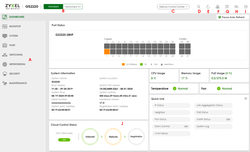
A – Click the menu items to open sub-menu links, and then click on a sub-menu link to open the screen in the main window.
B, C, D, E, F, G, H, I – These are quick links which allow you to perform certain tasks no matter which screen you are currently working in.
B – Click this icon to switch between the Web Configurator’s Standard or Networked AV mode (with Access L3 license only).
C – Click this icon to go to the NCC (Nebula Control Center) portal website.
D – Click this icon to search for specific configurations or status you are looking for. Enter the keywords and click the result link. This will direct you to the specific configuration or status page.
E – Click this icon to update the information in the screen you are currently viewing.
F – Click this icon to save your configuration into the Switch’s non-volatile memory. Non-volatile memory is the configuration of your Switch that stays the same even if the Switch’s power is turned off.
G – Click this icon to display web help pages. The help pages provide descriptions for all of the configuration screens.
H – Click this icon to go to the Zyxel Community Biz Forum.
I – Click this icon to log out of the Web Configurator.
J – This displays the Nebula Cloud Control Status. The ON/OFF switch displays if NCC Discovery is enabled. If a status circle turns Orange, it means the Switch is unable to connect to NCC. Hover the mouse over the status circle to check the diagnostic message. You can also click the ON/OFF switch to go to the SYSTEM > Cloud Management > Cloud Management screen and check the diagnostic messages. See SYSTEM > Cloud Management > Cloud Management for more information.
In the navigation panel, click a main link to reveal a list of sub-menu links.
The following table describes the links in the navigation panel. The navigation panel varies depending on the product model you use.
link | description |
|---|---|
DASHBOARD | This link takes you to the main dashboard screen that displays general system and device information. |
MONITOR | |
ARP Table | This link takes you to a screen that displays the current ARP table of the Switch. You can view the IP and MAC address mapping, VLAN ID, ARP aging time, and ARP entry type of a device attached to a port. |
IPv6 Neighbor Table | This link takes you to a screen where you can view the Switch’s IPv6 neighbor table. |
MAC Table | This link takes you to a screen where you can view the MAC address and VLAN ID of a device attach to a port. You can also view what kind of MAC address it is. |
Neighbor | This link takes you to a screen where you can view neighbor devices (including non-Zyxel devices) connected to the Switch. |
Path MTU Table | This link takes you to a screen where you can view the IPv6 path MTU information on the Switch. |
Port Status | This link takes you to a screen where you can view the port statistics. |
System Information | This link takes you to a screen that displays general system information. |
System Log | This link takes you to a screen where you can view the system log including fail log and system status. |
SYSTEM | |
Cloud Management | This link takes you to a screen where you can enable or disable the Nebula Control Center (NCC) Discovery feature and view the NCC connection status. If Nebula Control Center (NCC) Discovery is enabled, you can have the Switch search for the NCC (Nebula Control Center). The screen also displays a QR code containing the Switch’s serial number and MAC address for handy registration of the Switch at NCC. |
General Setup | This link takes you to a screen where you can configure general identification information about the Switch. |
Interface Setup | This link takes you to a screen where you can configure settings for individual interface type and ID. |
IP Setup | This link takes you to a screen where you can configure the DHCP client, and a static IP address (IP address and subnet mask). |
IPv6 | Click the link to unfold the following sub-link menu. |
IPv6 Status | This link takes you to a screen where you can view the IPv6 table and DNS server. |
IPv6 Global Setup | This link takes you to a screen where you can configure the global IPv6 settings. |
IPv6 Interface Setup | This link takes you to a screen where you can view and configure IPv6 interfaces. |
IPv6 Addressing | This link takes you to a screen where you can view and configure IPv6 link-local and global addresses. |
IPv6 Neighbor Discovery | This link takes you to a screen where you can view and configure neighbor discovery settings on each interface. |
IPv6 Neighbor Setup | configure static IPv6 neighbor entries in the Switch’s IPv6 neighbor table. |
DHCPv6 Client Setup | This link takes you to a screen where you can configure the Switch’s DHCP settings when it is acting as a DHCPv6 client. |
Logins | This link takes you to a screen where you can change the system login password, as well as configure up to four login details. |
SNMP | This link takes you to screens where you can specify the SNMP version and community (password) values, configure where to send SNMP traps from the Switch, enable loopguard/errdisable/poe/linkup/linkdown/lldp/transceiver-ddm/storm-control on the Switch, specify the types of SNMP traps that should be sent to each SNMP manager, and add/edit user information. |
Switch Setup | This link takes you to a screen where you can set up global Switch parameters such as VLAN type. |
Syslog Setup | This link takes you to a screen where you can configure the Switch’s system logging settings and configure a list of external syslog servers. |
Time Range | This link takes you to a screen where you can configure time range for time-oriented features like Classifier. |
PORT | |
Auto PD Recovery | This link takes you to a screen where you can enable and configure Auto PD Recovery on the Switch. |
Flex Link | This screen takes you to a screen where you can view configure backup links in the Data Link layer. |
Green Ethernet | This link takes you to a screen where you can configure the Switch to reduce port power consumption. |
Link Aggregation | This link takes you to a screen where you can logically aggregate physical links to form one logical, higher-bandwidth link. |
LLDP | Click the link to unfold the following sub-link menu. |
LLDP | This link takes you to screens where you can view LLDP information and configure LLDP and TLV settings. |
LLDP MED | This link takes you to screens where you can configure LLDP-MED parameters. |
OAM | This link takes you to screens where you can enable Ethernet OAM on the Switch, view the configuration of ports on which Ethernet OAM is enabled and perform remote-loopback tests. |
PoE Setup | For PoE models. This link takes you to a screen where you can set priorities, PoE power-up settings and schedule so that the Switch is able to reserve and allocate power to certain PDs. |
Port Setup | This link takes you to a screen where you can configure settings for individual Switch ports. |
ZULD | This link takes you to screens where you can enable ZULD on a port and configure related settings. |
SWITCHING | |
Layer 2 Protocol Tunneling | This link takes you to a screen where you can configure L2PT (Layer 2 Protocol Tunneling) settings on the Switch. |
Loop Guard | This link takes you to a screen where you can configure protection against network loops that occur on the edge of your network. |
Mirroring | Click the link to unfold the following sub-link menu. |
Mirroring | This link take you to a screen where you can copy traffic from one port or ports to another port in order to examine the traffic from the first port without interference. |
Multicast | Click the link to unfold the following sub-link menu. |
IPv4 Multicast | This link takes you to screens where you can configure various IPv4 multicast features, IGMP snooping, filtering and create multicast VLANs. |
IPv6 Multicast | This link takes you to screen where you can configure various IPv6 multicast features, MLD snooping-proxy, filtering and create multicast VLANs. |
MVR | This link takes you to screens where you can create multicast VLANs and select the receiver ports and a source port for each multicast VLAN. |
Static Multicast Forwarding By MAC | This link takes you to a screen where you can configure static multicast MAC addresses for port(s). These static multicast MAC addresses do not age out. |
PPPoE Intermediate Agent | This link takes you to screens where you can enable PPPoE (Point-to-Point Protocol over Ethernet) Intermediate Agent and configure per-port, per-port-per-VLAN settings. |
QoS | Click the link to unfold the following sub-link menu. |
Diffserv | This link takes you to screens where you can enable DiffServ, configure marking rules and set DSCP-to-IEEE802.1p mappings. |
Queuing Method | This link takes you to a screen where you can set priorities for the queues of the Switch. This distributes bandwidth across the different traffic queues. |
Priority Queue | This link takes you to a screen where you can set priority tags for different traffic types and specify the priority levels. |
Bandwidth Control | This link takes you to a screen where you can cap the maximum bandwidth allowed on a port. |
Spanning Tree Protocol | Click the link to unfold the following sub-link menu. |
Spanning Tree Protocol Status | This link takes you to a screen where you can view the STP status in the different STP modes (RSTP, MRSTP or MSTP) you can configure on the Switch. |
Spanning Tree Setup | This link takes you to a screen where you can activate one of the STP modes (RSTP, MRSTP or MSTP) on the Switch. |
RSTP | This link takes you to a screen where you can configure the RSTP (Rapid Spanning Tree Protocol) settings on the Switch. |
MRSTP | This link takes you to a screen where you can configure the MRSTP (Multiple Rapid Spanning Tree Protocol) settings on the Switch. |
MSTP | This link takes you to a screen where you can configure the MSTP (Multiple Spanning Tree Protocol) settings on the Switch. |
Static MAC Filtering | This link takes you to a screen to set up static MAC filtering rules. |
Static MAC Forwarding | This link takes you to a screen where you can configure static MAC addresses for a port. These static MAC addresses do not age out. |
VLAN | Click the link to unfold the following sub-link menu. |
VLAN Status | This link takes you to a screen where you can view and search all VLAN groups. |
VLAN Setup | This link takes you to screens where you can: • configure port-based or 802.1Q VLAN. • view detailed port settings and status of the VLAN group. • configure and view 802.1Q VLAN parameters for the Switch. • configure the static VLAN settings on a port. |
Subnet Based VLAN Setup | This link takes you to a screen where you can set up VLANs that allow you to group traffic into logical VLANs based on the source IP subnet you specify. |
Protocol Based VLAN Setup | This link takes you to a screen where you can set up VLANs that allow you to group traffic into logical VLANs based on the protocol you specify. |
Voice VLAN Setup | This link takes you to a screen where you can set up VLANs that allow you to group voice traffic with defined priority and enable the Switch port to carry the voice traffic separately from data traffic to ensure the sound quality does NOT deteriorate. |
MAC Based VLAN Setup | This link takes you to a screen where you can set up VLANs that allow you to group untagged packets into logical VLANs based on the source MAC address of the packet. This eliminates the need to reconfigure the Switch when you change ports. The Switch will forward the packets based on the source MAC address you set up previously. |
Vendor ID Based VLAN Setup | This link takes you to screens where you can set up VLANs that allow you to group untagged packets into logical VLANs based on the source MAC address of the packet. You can specify a mask for the MAC address to create a MAC address filter and enter a weight to set the VLAN rule’s priority. |
VLAN Isolation | This link takes you to a screen where you can block traffic between ports in a VLAN on the Switch. |
VLAN Mapping | This link takes you to screens where you can configure VLAN mapping settings on the Switch. |
VLAN Stacking | This link takes you to screens where you can activate and configure VLAN stacking. |
NETWORKING | |
ARP Setup | Click the link to unfold the following sub-link menu. |
ARP Learning | This link takes you to a screen where you can configure ARP learning mode on a per-port basis. |
DHCP | Click the link to unfold the following sub-link menu. |
DHCPv4 Relay | This link takes you to screens where you can view DHCPv4 relay status, mode, and configure DHCPv4 relay settings. |
DHCPv6 Relay | This link takes you to a screen where you can enable and configure DHCPv6 relay. |
DHCP Server Guard | This link takes you to a screen where you can specify whether ports are trusted or untrusted ports for DHCP packets. |
Static Routing | Click the link to unfold the following sub-link menu. |
IPv4 Static Route | This link takes you to a screen where you can configure IPv4 static routes. A static route defines how the Switch should forward traffic by destination IP address and subnet mask. |
SECURITY | |
AAA | Click the link to unfold the following sub-link menu. |
RADIUS Server Setup | This link takes you to a screen where you can configure your RADIUS (Remote Authentication Dial-In User Service) server settings for authentication. |
TACACS+ Server Setup | This link takes you to a screen where you can configure your TACACS+ (Terminal Access Controller Access Control System Plus) server settings for authentication. |
AAA Setup | This link takes you to a screen where you can configure authentication, authorization and accounting services through external servers. The external servers can be either RADIUS or TACACS+ (Terminal Access Controller Access Control System Plus). |
Access Control | Click the link to unfold the following sub-link menu. |
Service Access Control | This link takes you to a screen where you can decide what services you may use to access the Switch. |
Remote Management | This link takes you to a screen where you can specify a group of one or more “trusted computers” from which an administrator may use a service to manage the Switch. |
Account Security | This link takes you to a screen where you can configure account security settings on the Switch. |
ACL | Click the link to unfold the following sub-link menu. |
Classifier | This link takes you to screens where you can configure the Switch to group packets based on the specified criteria. |
Policy Rule | This link takes you to a screen where you can configure the Switch to perform special treatment on the grouped packets. |
Anti-Arpscan | This link takes you to screens where you can enable anti-arpscan on the Switch and ports, and view the port state. You can also create trusted hosts, view blocked hosts and unblock them. |
BPDU Guard | This link takes you to screens where you can enable BPDU guard on the Switch and ports, and view the port state. |
Storm Control | This link takes you to a screen to set up broadcast filters. |
Errdisable | This link takes you to screens where you can view errdisable status and configure errdisable settings in CPU protection, errdisable detect, and errdisable recovery. |
IPv4 Source Guard | Click the link to unfold the following sub-link menu. |
IP Source Guard | This link takes you to screens where you can configure filtering of unauthorized DHCP and ARP packets in your network. |
DHCP Snooping | This link takes you to screens where you can view DHCP snooping database details and configure DHCP snooping settings on ports or VLANs. You can use DHCP snooping to filter unauthorized DHCP packets on the network and to build the binding table dynamically. |
ARP Inspection | This link takes you to screens where you can view ARP inspection status, and configure ARP inspection settings on ports or VLANs. You can use ARP inspection to filter unauthorized ARP packets on the network. |
IPv6 Source Guard | Click the link to unfold the following sub-link menu. |
IPv6 Static Binding | The link takes you to screens where you can view IPv6 static binding status and manually create IPv6 source guard static binding entries. |
IPv6 Source Guard | The link takes you to screens where you can define policies to have IPv6 source guard forward valid addresses and/or prefixes and allow or block data traffic from all link-local addresses, and apply the configured IPv6 source guard policy to a port. |
IPv6 Snooping | The link takes you to screens where you can set up DHCPv6 snooping policies for the binding table and enable the policies on VLAN interfaces. |
DHCPv6 Trust Setup | The link takes you to a screen where you can specify which ports are trusted for DHCPv6 snooping. |
Port Authentication | Click the link to unfold the following sub-link menu. These links take you to screens where you can configure IEEE 802.1x port authentication as well as MAC authentication for clients communicating through the Switch. |
802.1x | The link takes you to a screen where you can activate IEEE 802.1x security on a port. |
MAC Authentication | The link takes you to a screen where you can activate MAC authentication on a port. |
Guest VLAN | The link takes you to a screen where you can activate enable and assign a guest VLAN to a port. |
Compound Authentication Mode | The link takes you to a screen where you can allow network access for clients that pass either IEEE 802.1x authentication or MAC authentication, or pass both IEEE 802.1x authentication and MAC authentication. |
Port Security | This link takes you to a screen where you can activate MAC address learning and set the maximum number of MAC addresses to learn on a port. |
MAINTENANCE | |
Certificates | The link takes you to a screen where you can import the Switch's CA-signed certificates. |
Cluster Management | This link takes you to a screen where you can configure clustering management and view its status. |
Configuration | Click the link to unfold the following sub-link menu. |
Restore Configuration | This link takes you to a screen where you can upload a stored device configuration file. |
Backup Configuration | This link takes you to a screen where you can save your Switch’s configurations (settings) for later use. |
Auto Configuration | This link takes you to a screen where you can overwrite the running configuration stored in the Switch’s RAM. |
Erase Running-Configuration | This link takes you to a screen where you can reset the configuration to the Zyxel default configuration settings. |
Save Configuration | This link takes you to a screen where you can save the current configuration (settings) to a specific configuration file on the Switch. |
Configure Clone | This link takes you to a screen where you can copy the basic and advanced settings from a source port to a destination port or ports. |
Diagnostic | This link takes you to a screen where you can ping IP addresses, run traceroute, test ports and show the location of the Switch. |
Firmware Upgrade | This link takes you to a screen to upload firmware to your Switch. |
Reboot System | This link takes you to a screen to reboot the Switch without turning the power off. |
SSH Authorized Keys | This link takes you to a screen where you can authenticate secure SSH connections between a client computer and the Switch (also called the server) without needing a password to connect to the Switch. |
SSH Host Keys | This link takes you to a screen where you can regenerate the Switch's SSH host key. |
Tech-Support | This link takes you to a screen where you can download related log reports for issue analysis. Log reports include CPU history and utilization, crash and memory. |
The following table describes the links in the navigation panel when the Switch is in Networked AV mode.
link | description |
|---|---|
SUMMARY | This screen displays the Switch’s front panel port status, connected ports, used power, Nebula Cloud Control status, and Networked AV status. |
MONITOR | |
System Information | This link takes you to a screen that displays general system information. |
SYSTEM | |
Cloud Management | This screen displays a link to a screen where you can enable or disable the Nebula Control Center (NCC) Discovery feature. If it is enabled, you can have the Switch search for the NCC (Nebula Control Center). The screen also has a QR code containing the Switch’s serial number and MAC address for handy registration of the Switch at NCC. |
General Setup | This link takes you to a screen where you can configure general identification information about the Switch. |
IP Setup | This screen allows you to configure the IP address and subnet mask (necessary for Switch management) and set up to 64 IP routing domains. |
Logins | This link takes you to a screen where you can change the system login password, as well as configure up to four login details. |
SNMP | This link takes you to screens where you can specify the SNMP version and community (password) values, configure where to send SNMP traps from the Switch, enable loopguard/errdisable/poe/linkup/linkdown/lldp/transceiver-ddm/storm-control on the Switch, specify the types of SNMP traps that should be sent to each SNMP manager, and add/edit user information. |
PORT | |
Link Aggregation | This link takes you to screens where you can logically aggregate physical links to form one logical, higher-bandwidth link. |
PoE Setup | For PoE models. This link takes you to a screen where you can set priorities, PoE power-up settings and schedule so that the Switch is able to reserve and allocate power to certain PDs. |
Port Setup | This screen allows you to configure settings for individual Switch ports. |
SWITCHING | |
Diffserv | This link takes you to screens where you can enable DiffServ, configure marking rules and set DSCP-to-IEEE802.1p mappings. |
Mirroring | This link takes you to screens where you can copy traffic from one port or ports to another port in order that you can examine the traffic from the first port without interference. |
Multicast | This link takes you to screens where you can view multicast group information, configure various multicast features like IGMP snooping and filtering profile, and create multicast VLANs. |
IPv4 Multicast | This link takes you to screens where you can configure various IPv4 multicast features, IGMP snooping, filtering and create multicast VLANs. |
Static Multicast Forwarding By MAC | This link takes you to a screen where you can configure static multicast MAC addresses for port(s). These static multicast MAC addresses do not age out. |
VLAN | This link takes you to screens where you can view and search all static VLAN groups, view detailed port settings and status of the static VLAN group, configure a static VLAN for the Switch, and configure the static VLAN (IEEE 802.1Q) settings on a port. |
SECURITY | |
Access Control | |
Service Access Control | This link takes you to a screen where you can decide what services you may use to access the Switch. |
Remote Management | This link takes you to a screen where you can specify a group of one or more “trusted computers” from which an administrator may use a service to manage the Switch. |
Storm Control | This link takes you to a screen to set up broadcast filters. |
MAINTENANCE | |
Configuration | |
Restore Configuration | This link takes you to a screen where you can upload a stored device configuration file. |
Backup Configuration | This link takes you to a screen where you can save your Switch’s configurations (settings) for later use. |
Save Configuration | This link takes you to a screen where you can save the current configuration (settings) to a specific configuration file on the Switch. |
Firmware Upgrade | This link takes you to a screen to upload firmware to your Switch. |
Reboot System | This link takes you to a screen to reboot the Switch without turning the power off. |
Tech-Support | This link takes you to a screen where you can download related log reports for issue analysis. Log reports include CPU history and utilization, crash and memory. |
Save Your Configuration
When you are done modifying the settings in a screen, click Apply to save your changes back to the run-time memory. Settings in the run-time memory are lost when the Switch’s power is turned off.
Click the Save link in the upper right of the Web Configurator to save your configuration to non-volatile memory. Non-volatile memory refers to the Switch’s storage that remains even if the Switch’s power is turned off.
Switch Lockout
You could block yourself (and all others) from using in-band-management (managing through the data ports) if you do one of the following:
1 Delete the management VLAN (default is VLAN 1).
2 Delete all port-based VLANs with the CPU port as a member. The “CPU port” is the management port of the Switch.
3 Filter all traffic to the CPU port.
4 Disable all ports.
5 Misconfigure the text configuration file.
6 Forget the password and/or IP address.
7 Prevent all services from accessing the Switch.
8 Change a service port number but forget it.
9 You forgot to log out of the Switch from a computer before logging in again on another computer.
Reset the Switch
If you lock yourself (and others) from the Switch or forget the administrator password, you will need to reload the factory-default configuration file or reset the Switch back to the factory defaults.
Restore Button
Press the RESTORE button for more than 7 seconds to have the Switch automatically reboot and restore the factory default file.
Restore Custom Default (Standalone mode only)
Press the RESTORE button for 3 to 7 seconds to have the Switch automatically reboot and restore the last-saved custom default file. See LEDs for more information about the LED behavior.
Reboot the Switch
Press the RESET button to reboot the Switch without turning the power off. See LEDs for more information about the LED behavior.
Log Out of the Web Configurator
Click Logout in a screen to exit the Web Configurator. You have to log in with your password again after you log out. This is recommended after you finish a management session for security reasons.
Logout button