Interfaces
Interface Overview
Use the Interface screens to configure the Zyxel Device’s interfaces. You can also create interfaces on top of other interfaces.
• Ports are the physical ports to which you connect cables.
• Interfaces are used within the system operationally. You use them in configuring various features. An interface also describes a network that is directly connected to the Zyxel Device. For example, You connect the LAN network to the LAN interface.
What You Can Do in this Chapter
• Use the Interface (Interface Screen) screen to view a summary of the Zyxel Device interface settings.
• Use the Internal/External/General Interface (Internal Interface) screens to configure Ethernet, VLAN, and bridge interfaces.
Ethernet interfaces are the foundation for defining other interfaces and network policies.
VLAN interfaces receive and send tagged frames. The Zyxel Device automatically adds or removes the tags as needed.
Bridge interfaces combine two or more network segments into a single network.
LAG interfaces combine multiple physical Ethernet interfaces into a single logical interface.
What You Need to Know
Interface Characteristics
Interfaces generally have the following characteristics (although not all characteristics apply to each type of interface).
• An interface is a logical entity through which (layer-3) packets pass.
• An interface is bound to a physical port or another interface.
• Many interfaces can share the same physical port.
• An interface belongs to at most one zone.
• Many interfaces can belong to the same zone.
Types of Interfaces
You can create several types of interfaces in the Zyxel Device.
• Setting interfaces to the same port role forms a port group. Port groups creates a hardware connection between physical ports at the layer-2 (data link, MAC address) level. Port groups are created when you use the Interface > Port screen to set multiple physical ports to be part of the same interface.
model | Individual Ports |
|---|---|
USG FLEX 500H | P1, P2 |
USG FLEX 700H | P1, P2, P13, P14 |
• Ethernet interfaces are the foundation for defining other interfaces and network policies.
• VLAN interfaces receive and send tagged frames. The Zyxel Device automatically adds or removes the tags as needed.
• Bridge interfaces create a software connection between Ethernet or VLAN interfaces at the layer-2 (data link, MAC address) level. Unlike port groups, bridge interfaces can take advantage of some security features in the Zyxel Device. You can also assign an IP address and subnet mask to the bridge.
• Trunk interfaces manage load balancing between interfaces.
• PPPoE interfaces support Point-to-Point Protocols (PPP). ISP accounts are required for PPPoE interfaces.
• VPN Tunnel Interface (VTI) encrypts or decrypts IPv4 traffic from or to the interface according to the IP routing table.
• Link Aggregation Group (LAG) interfaces combine multiple physical Ethernet interfaces into a single logical interface, thus increasing uplink bandwidth and availability in the event a link goes down.
See the following table for interface types and supported features.
ROLES | external | internal | general |
|---|---|---|---|
Characteristics | Ethernet VLAN Bridge LAG PPPoE | Ethernet VLAN Bridge LAG | Ethernet VLAN Bridge LAG |
Configurable Zone | Yes | Yes | Yes |
Static IP address | Yes | Yes | Yes |
DHCP client | Yes | No | Yes |
DHCP server/relay | No | Yes | Yes |
Default SNAT | Yes | No | No |
Packet size (MTU) | Yes | Yes | Yes |
Connectivity Check | Yes | Yes | Yes |
Relationships Between Interfaces
In the Zyxel Device, interfaces are usually created on top of other interfaces. Only Ethernet interfaces are created directly on top of the physical ports or port groups. The relationships between interfaces are explained in the following table.
Interface | restriction | Required Port / Interface |
|---|---|---|
Ethernet interface | N/A | physical port |
LAG | When you configure a LAG interface, you cannot set the LAG interface on an Ethernet interface that is already used by other interfaces. | Ethernet interface |
Bridge interface | When you configure a bridge interface, you cannot set the bridge interface on an interface that is already used by other bridge or VLAN interfaces. | Ethernet interface* VLAN interface* |
Trunk | When you configure a trunk interface, you cannot set the trunk interface on an interface that is already used by other bridge or LAG interfaces. | External/General Ethernet interface VLAN interface LAG interface PPPoE interface bridge interface |
PPPoE interface | N/A | Ethernet interface* VLAN interface* bridge interface |
Bridge Overview
A bridge creates a connection between two or more network segments at the layer-2 (MAC address) level. When the bridge receives a packet, the bridge records the source MAC address and the port on which it was received in a table. It also looks up the destination MAC address in the table. If the bridge knows on which port the destination MAC address is located, it sends the packet to that port. If the destination MAC address is not in the table, the bridge broadcasts the packet on every port (except the one on which it was received).
In the example above, computer A sends a packet to computer B. Bridge X records the source address 0A:0A:0A:0A:0A:0A and port 2 in the table. It also looks up 0B:0B:0B:0B:0B:0B in the table. There is no entry yet, so the bridge broadcasts the packet on ports 1, 3, and 4.
MAC Address | Port |
|---|---|
0A:0A:0A:0A:0A:0A | 2 |
If computer B responds to computer A, bridge X records the source address 0B:0B:0B:0B:0B:0B and port 4 in the table. It also looks up 0A:0A:0A:0A:0A:0A in the table and sends the packet to port 2 accordingly.
MAC Address | Port |
|---|---|
0A:0A:0A:0A:0A:0A | 2 |
0B:0B:0B:0B:0B:0B | 4 |
Bridge Interface Overview
A bridge interface creates a software bridge between the members of the bridge interface. It also becomes the Zyxel Device’s interface for the resulting network.
The Zyxel Device can bridge traffic between some interfaces while it routes traffic for other interfaces. The bridge interfaces also support functions like interface bandwidth parameters, DHCP settings, and connectivity check. To use the whole Zyxel Device as a transparent bridge, add all of the Zyxel Device’s interfaces to a bridge interface.
A bridge interface may consist of the following members:
• Zero or one VLAN interfaces (and any associated virtual VLAN interfaces)
• Any number of Ethernet interfaces (and any associated virtual Ethernet interfaces)
When you create a bridge interface, the Zyxel Device removes the members’ entries from the routing table and adds the bridge interface’s entries to the routing table. For example, this table shows the routing table before and after you create bridge interface br0 (250.250.250.0/23) between lan1 and vlan1.
IP Address(es) | Destination | IP Address(es) | Destination | |
|---|---|---|---|---|
210.210.210.0/24 | lan1 | 221.221.221.0/24 | vlan0 | |
210.211.1.0/24 | lan1:1 | 230.230.230.192/26 | wan2 | |
221.221.221.0/24 | vlan0 | 241.241.241.241/32 | dmz | |
222.222.222.0/24 | vlan1 | 242.242.242.242/32 | dmz | |
230.230.230.192/26 | wan2 | 250.250.250.0/23 | br0 | |
241.241.241.241/32 | dmz | |||
242.242.242.242/32 | dmz |
In this example, virtual Ethernet interface lan1:1 is also removed from the routing table when lan1 is added to br0. Virtual interfaces are automatically added to or remove from a bridge interface when the underlying interface is added or removed.
IP Address Assignment
Most interfaces have an IP address and a subnet mask.
This information is used to create an entry in the routing table.
IP Address(es) | Destination |
|---|---|
100.100.1.1/16 | lan1 |
200.200.200.1/24 | wan1 |
For example, if the Zyxel Device gets a packet with a destination address of 100.100.25.25, it routes the packet to interface lan1. If the Zyxel Device gets a packet with a destination address of 200.200.200.200, it routes the packet to interface wan1.
In most interfaces, you can enter the IP address and subnet mask manually. In PPPoE interfaces, however, the subnet mask is always 255.255.255.255 because it is a point-to-point interface. For these interfaces, you can only enter the IP address.
In many interfaces, you can also let the IP address and subnet mask be assigned by an external DHCP server on the network. In this case, the interface is a DHCP client. Virtual interfaces, however, cannot be DHCP clients. You have to assign the IP address and subnet mask manually.
In general, the IP address and subnet mask of each interface should not overlap, though it is possible for this to happen with DHCP clients.
In the example above, if the Zyxel Device gets a packet with a destination address of 5.5.5.5, it might not find any entries in the routing table. In this case, the packet is dropped. However, if there is a default router to which the Zyxel Device should send this packet, you can specify it as a gateway in one of the interfaces. For example, if there is a default router at 200.200.200.100, you can create a gateway at 200.200.200.100 on ge2. In this case, the Zyxel Device creates the following entry in the routing table.
IP Address(es) | Destination |
|---|---|
0.0.0.0/0 | 200.200.200.100 |
The gateway is an optional setting for each interface. If there is more than one gateway, the Zyxel Device uses the gateway with the lowest metric, or cost. If two or more gateways have the same metric, the Zyxel Device uses the one that was set up first (the first entry in the routing table). In PPPoE interfaces, the other computer is the gateway for the interface by default. In this case, you should specify the metric.
If the interface gets its IP address and subnet mask from a DHCP server, the DHCP server also specifies the gateway, if any.
DHCP Settings
Dynamic Host Configuration Protocol (DHCP, RFC 2131, RFC 2132) provides a way to automatically set up and maintain IP addresses, subnet masks, gateways, and some network information (such as the IP addresses of DNS servers) on computers on the network. This reduces the amount of manual configuration you have to do and usually uses available IP addresses more efficiently.
In DHCP, every network has at least one DHCP server. When a computer (a DHCP client) joins the network, it submits a DHCP request. The DHCP servers get the request; assign an IP address; and provide the IP address, subnet mask, gateway, and available network information to the DHCP client. When the DHCP client leaves the network, the DHCP servers can assign its IP address to another DHCP client.
In the Zyxel Device, some interfaces can provide DHCP services to the network. In this case, the interface can be a DHCP relay or a DHCP server.
As a DHCP relay, the interface routes DHCP requests to DHCP servers on different networks. You can specify more than one DHCP server. If you do, the interface routes DHCP requests to all of them. It is possible for an interface to be a DHCP relay and a DHCP client simultaneously.
As a DHCP server, the interface provides the following information to DHCP clients.
• IP address - If the DHCP client’s MAC address is in the Zyxel Device’s static DHCP table, the interface assigns the corresponding IP address. If not, the interface assigns IP addresses from a pool, defined by the starting address of the pool and the pool size.
Start IP Address | Pool Size | Range of Assigned IP Address |
|---|---|---|
50.50.50.33 | 5 | 50.50.50.33 - 50.50.50.37 |
75.75.75.1 | 200 | 75.75.75.1 - 75.75.75.200 |
99.99.1.1 | 1023 | 99.99.1.1 - 99.99.4.255 |
120.120.120.100 | 100 | 120.120.120.100 - 120.120.120.199 |
The Zyxel Device cannot assign the first address (network address) or the last address (broadcast address) on the subnet defined by the interface’s IP address and subnet mask. For example, in the first entry, if the subnet mask is 255.255.255.0, the Zyxel Device cannot assign 50.50.50.0 or 50.50.50.255. If the subnet mask is 255.255.0.0, the Zyxel Device cannot assign 50.50.0.0 or 50.50.255.255. Otherwise, it can assign every IP address in the range, except the interface’s IP address.
If you do not specify the starting address or the pool size, the interface the maximum range of IP addresses allowed by the interface’s IP address and subnet mask. For example, if the interface’s IP address is 9.9.9.1 and subnet mask is 255.255.255.0, the starting IP address in the pool is 9.9.9.2, and the pool size is 253.
• Subnet mask - The interface provides the same subnet mask you specify for the interface. See IP Address Assignment .
• Gateway - The interface provides the same gateway you specify for the interface. See IP Address Assignment .
• DNS servers - The interface provides IP addresses for up to three DNS servers that provide DNS services for DHCP clients. You can specify each IP address manually (for example, a company’s own DNS server), or you can refer to DNS servers that other interfaces received from DHCP servers (for example, a DNS server at an ISP). These other interfaces have to be DHCP clients.
It is not possible for an interface to be the DHCP server and a DHCP client simultaneously.
WINS
WINS (Windows Internet Naming Service) is a Windows implementation of NetBIOS Name Server (NBNS) on Windows. It keeps track of NetBIOS computer names. It stores a mapping table of your network’s computer names and IP addresses. The table is dynamically updated for IP addresses assigned by DHCP. This helps reduce broadcast traffic since computers can query the server instead of broadcasting a request for a computer name’s IP address. In this way WINS is similar to DNS, although WINS does not use a hierarchy (unlike DNS). A network can have more than one WINS server. Samba can also serve as a WINS server.
PPPoE Overview
Point-to-Point Protocol over Ethernet (PPPoE, RFC 2516) is usually used to connect two computers over phone lines or broadband connections. PPPoE is often used with cable modems and DSL connections. It provides the following advantages:
• The access and authentication method works with existing systems, including RADIUS.
• You can access one of several network services. This makes it easier for the service provider to offer the service
• PPPoE does not usually require any special configuration of the modem.
VLANs
A Virtual Local Area Network (VLAN) divides a physical network into multiple logical networks. The standard is defined in IEEE 802.1q.
In this example, there are two physical networks and three departments A, B, and C. The physical networks are connected to hubs, and the hubs are connected to the router.
Alternatively, you can divide the physical networks into three VLANs.
Each VLAN is a separate network with separate IP addresses, subnet masks, and gateways. Each VLAN also has a unique identification number (ID). The ID is a 12-bit value that is stored in the MAC header. The VLANs are connected to switches, and the switches are connected to the router. (If one switch has enough connections for the entire network, the network does not need switches A and B.)
• Traffic inside each VLAN is layer-2 communication (data link layer, MAC addresses). It is handled by the switches. As a result, the new switch is required to handle traffic inside VLAN 2. Traffic is only broadcast inside each VLAN, not each physical network.
• Traffic between VLANs (or between a VLAN and another type of network) is layer-3 communication (network layer, IP addresses). It is handled by the router.
This approach provides a few advantages.
• Increased performance - In VLAN 2, the extra switch should route traffic inside the sales department faster than the router does. In addition, broadcasts are limited to smaller, more logical groups of users.
• Higher security - If each computer has a separate physical connection to the switch, then broadcast traffic in each VLAN is never sent to computers in another VLAN.
• Better manageability - You can align network policies more appropriately for users. For example, you can create different content filtering rules for each VLAN (each department in the example above), and you can set different bandwidth limits for each VLAN. These rules are also independent of the physical network, so you can change the physical network without changing policies.
In this example, the new switch handles the following types of traffic:
• Inside VLAN 2.
• Between the router and VLAN 1.
• Between the router and VLAN 2.
• Between the router and VLAN 3.
In the Zyxel Device, each VLAN is called a VLAN interface. As a router, the Zyxel Device routes traffic between VLAN interfaces, but it does not route traffic within a VLAN interface. All traffic for each VLAN interface can go through only one Ethernet interface, though each Ethernet interface can have one or more VLAN interfaces.
Otherwise, VLAN interfaces are similar to other interfaces in many ways. They have an IP address, subnet mask, and gateway used to make routing decisions. They restrict bandwidth and packet size. They can provide DHCP services, and they can verify the gateway is available.
LAG
Link Aggregation Group (LAG) is a way to combine multiple physical Ethernet interfaces into a single logical interface. This increases uplink bandwidth. It also increases availability as even if a member link goes down, LAG can continue to transmit and receive traffic over the remaining links.
To configure LAG, configure a link number and specify the member ports in the link. All ports must have the same speed and be in full-duplex mode. You must configure the LAG on both sides of the link and you must set the interfaces on either side of the link to be the same speed.
Ethernet interfaces available to join a LAG interface must fulfill the following criteria.
1 The interface cannot be in another LAG. If an interface is in another LAG, it is not available to join the LAG interface until you remove the interface from the other LAG.
2 The interface cannot be in a VLAN or PPPoE. If the interfaces is bound to an interface that is in a VLAN or PPPoE, the interface is not available to join the LAG interface until you remove the interface from the VLAN or PPPoE.
3 The selected interface must be bound to only 1 physical port.
• If you select an interface that has no ports bound to it, you must bind a port to this interface.
• If you select an interface that has more than one port bound to it, you must remove all ports but one from this interface.
Interface Screen
Use this screen to view your Zyxel Device interface settings. To access this screen, click Network > Interface > Interface.
Add an interface to which type of network you will connect. When you select Internal, External or General, the rest of the screen’s options automatically adjust to correspond.
• The External interface is for connecting to an external network (like the Internet). The Zyxel Device automatically adds this interface to the default WAN trunk.
• The Internal interface is for connecting to a local network. Other corresponding configuration options: DHCP server and DHCP relay. The Zyxel Device automatically adds default SNAT settings for traffic flowing from this interface to an external interface; for example LAN to WAN traffic.
• The General interface is for connecting to either an external network or a local network. Select this option when you want full flexibility to manually define specific routing, NAT, or security rules without the automatic settings applied to Internal or External interfaces.
Interface Screen Warning Messages
Nebula VPN allows Zyxel Devices from different sites in an organization to communicate through a VPN.
The following reminder appears on the the Network > Interface > Interface screen if Nebula VPN is enabled. If you change IP addresses locally, there may be a conflict that would impact Nebula VPN.
The following warning appears if Nebula VPN is enabled and you are removing an interface. This may disrupt Nebula VPN. Ensure your Zyxel Device’s local IP address and network mask are different from those used by local networks behind other Zyxel Devices participating in Nebula VPN.
Subnet Change Warning 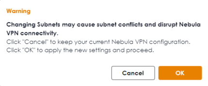
The following warning appears if Nebula VPN is enabled and you are removing an interface. This may disrupt Nebula VPN. Ensure you do not remove a subnet interface that is participating in the organization’s VPN in the NCC.
Interface Removal Warning 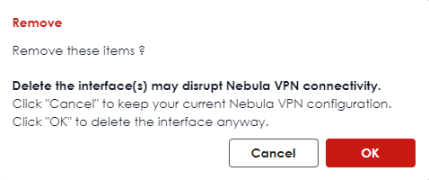
Each field is described in the following table.
Label | Description |
|---|---|
External | |
Add | Click this to add a new entry. |
Edit | Select an entry and click Edit to open a screen where you can modify the entry’s settings. |
Remove | To remove a virtual interface, select it and click Remove. The Zyxel Device confirms you want to remove it before doing so. |
Reference | This field displays the objects this entry uses. |
Active | To turn on an entry, select it and click Active. The Status light changes accordingly. |
Inactive | To turn off an entry, select it and click Inactive. The Status light changes accordingly. |
Connect | To dial-up to a PPPoE interface, select it and click Connect. |
Disconnect | To disconnect from a PPPoE interface, select it and click Disconnect. |
Status | This icon is lit when the entry is active and dimmed when the entry is inactive. |
Name | This field displays the name of the interface. |
Zone | This displays the zone to which this interface belongs. An interface can only be in one zone. |
Description | This field displays the description of the interface. |
IP/Netmask | This field displays the current IP address and the subnet mask of the interface. If this field is empty, the interface does not have an IP address yet. |
VLAN ID | This field displays the VLAN ID which is a 12-bit number that uniquely identifies each VLAN. |
Type | This field displays the interface type: Ethernet or VLAN. |
Ports | This field displays the port the interface is using. |
Reference | This field displays how many objects this entry uses. |
Internal | |
Add | Click this to add a new entry. |
Edit | Select an entry and click Edit to open a screen where you can modify the entry’s settings. |
Remove | To remove a virtual interface, select it and click Remove. The Zyxel Device confirms you want to remove it before doing so. |
Reference | This field displays the objects this entry uses. |
Active | To turn on an entry, select it and click Active. The Status light changes accordingly. |
Inactive | To turn off an entry, select it and click Inactive. The Status light changes accordingly. |
Status | This icon is lit when the entry is active and dimmed when the entry is inactive. |
Name | This field displays the name of the interface. |
Zone | This displays the zone to which this interface belongs. An interface can only be in one zone. |
Description | This field displays the description of the interface. |
IP/Netmask | This field displays the current IP address and the subnet mask of the interface. If this field is empty, the interface does not have an IP address yet. |
VLAN ID | This field displays the VLAN ID which is a 12-bit number that uniquely identifies each VLAN. |
Type | This field displays the interface type. |
Members | This field displays the port the interface is using. |
Reference | This field displays how many objects this entry uses. |
Advanced Settings | |
General | |
Add | Click this to add a new entry. |
Edit | Select an entry and click Edit to open a screen where you can modify the entry’s settings. |
Remove | To remove a general interface, select it and click Remove. The Zyxel Device confirms you want to remove it before doing so. |
Reference | This field displays the objects this entry uses. |
Active | To turn on an entry, select it and click Active. The Status light changes accordingly. |
Inactive | To turn off an entry, select it and click Inactive. The Status light changes accordingly. |
Status | This icon is lit when the entry is active and dimmed when the entry is inactive. |
Name | This field displays the name of the interface. |
Zone | This displays the zone to which this interface belongs. An interface can only be in one zone. |
Description | This field displays the description of the interface. |
IP/Netmask | This field displays the current IP address and the subnet mask of the interface. If this field is empty, the interface does not have an IP address yet. |
VLAN ID | This field displays the VLAN ID which is a 12-bit number that uniquely identifies each VLAN. |
Type | This field displays the interface type. |
Members | This field displays the Ethernet interfaces and VLAN interfaces in the bridge interface. It is blank for virtual interfaces. |
Reference | This field displays how many objects this entry uses. |
VTI | |
Edit | Select an entry and click Edit to open a screen where you can modify the entry’s settings. |
Remove | To remove a virtual interface, select it and click Remove. The Zyxel Device confirms you want to remove it before doing so. |
Reference | This field displays the objects this entry uses. |
Active | To turn on an entry, select it and click Active. The Status light changes accordingly. |
Inactive | To turn off an entry, select it and click Inactive. The Status light changes accordingly. |
Status | This icon is lit when the entry is active and dimmed when the entry is inactive. |
Name | This field displays the name of the interface. |
Zone | This displays the zone to which this interface belongs. An interface can only be in one zone. |
Use this screen to configure the external interface settings for connecting to an external network (like the Internet). The Zyxel Device automatically adds an external interface to the default WAN trunk.
External Interface Add/Edit
Unlike other types of interfaces, you cannot create new Ethernet interfaces nor can you delete any of them. If an Ethernet interface does not have any physical ports assigned to it, the Ethernet interface is effectively removed from the Zyxel Device, but you can still configure it.
Ethernet interfaces are similar to other types of interfaces in many ways. They have an IP address, subnet mask, and gateway used to make routing decisions. They restrict the amount of bandwidth and packet size. They can provide DHCP services, and they can verify the gateway is available.
Use Ethernet interfaces to control which physical ports exchange routing information with other routers and how much information is exchanged through each one. The more routing information is exchanged, the more efficient the routers should be. However, the routers also generate more network traffic, and some routing protocols require a significant amount of configuration and management.
These screen’s fields are described in the table below.
Label | Description |
|---|---|
General Settings | |
Enable Interface | Select this to enable this interface. Clear this to disable this interface. |
Interface Properties | |
Role | External is for connecting to an external network (like the Internet). The Zyxel Device automatically adds this interface to the default WAN trunk. |
Interface Type | Select the type of interface you want to configure. Select Ethernet to establish the foundation for defining other interfaces and network policies. Select VLAN to receive and send tagged frames. The Zyxel Device automatically adds or removes the tags as needed. Select Bridge to create a single network between Ethernet or VLAN interfaces at the layer-2 (data link, MAC address) level. Unlike port groups, bridge interfaces can take advantage of some security features in the Zyxel Device, such as Policy Control and IP Exception. You can also assign an IP address and subnet mask to the bridge. Select LAG to combine multiple ports into a single logical interface to increase bandwidth and provide redundancy. |
Name | Specify a name for the interface. It can use alphanumeric characters, hyphens, and underscores, and it can be up to 11 characters long. |
Port | This is the name of the Ethernet interface’s physical port. |
Member | This field displays when you select the VLAN Interface Type. Select the Ethernet interface on which the VLAN interface runs. |
Zone | Select the zone to which this interface is to belong. You use zones to apply security settings such as security policy, IPS, remote management, anti-malware, and application patrol. Make sure to select the correct zone as otherwise traffic may be blocked by a security policy. |
MAC Address | Have the interface use either the factory assigned default MAC address, a manually specified MAC address, or clone the MAC address of another device or computer. |
Use Default MAC Address | Select this option to have the interface use the factory assigned default MAC address. By default, the Zyxel Device uses the factory assigned MAC address to identify itself. |
Overwrite Default MAC Address | Select this option to have the interface use a different MAC address. Enter a MAC address in the format "xx:xx:xx:xx:xx:xx" or "xx-xx-xx-xx-xx-xx". Once it is successfully configured, the address will be copied to the configuration file. It will not change unless you change the setting or upload a different configuration file. |
VLAN ID | This field displays when you select the VLAN Interface Type. Enter the VLAN ID. This 12-bit number uniquely identifies each VLAN. Allowed values are 1 - 4094. (0 and 4095 are reserved.) |
Priority (802.1P) | This field displays when you select the VLAN Interface Type. Type a number between 0 and 7 to set the priority for the outgoing traffic from this interface. The bigger the number, the higher the priority. |
Description | Enter a description of this interface. You can use alphanumeric and ()+/:=?!*#@$_%- characters, and it can be up to 60 characters long. Spaces are allowed, but the string can’t start with a space. |
Address Assignment | These IP address fields configure an IPv4 IP address on the interface itself. If you change this IP address on the interface, you may also need to change a related address object for the network connected to the interface. For example, if you use this screen to change the IP address of your LAN interface, you should also change the corresponding LAN subnet address object. |
Unassigned | Select this if you don’t want to specify an IP address for this interface. |
Get Automatically (DHCP) | Select this to make the interface a DHCP client and automatically get the IP address, subnet mask, and gateway address from a DHCP server. |
Use Fixed IP Address | Select this if you want to specify the IP address, subnet mask, and gateway manually. • IP/Network Mask: You must enter the primary IP address to identify the WAN interface’s address for sending traffic with other network devices. • Gateway IP: Enter the IP address of the router through which this WAN connection will send traffic. |
Secondary IP | This is available when you select Use Fixed IP Address. An interface can be bound to three additional public IP addresses. You can assign these IP addresses to different servers on the same interface, enabling the servers to receive traffic using different IP addresses and ports. |
Add | Click this to bind up to three additional IP addresses to this interface. |
Remove | To remove a secondary IP address, select it and click Remove. The Zyxel Device confirms you want to remove it before doing so. |
IP/Netmask | Enter the secondary IP address and subnet mask to bind to this interface. |
Members | This is available when you select Bridge or LAG interface type. |
Add | Click this to add a new interface. You can add up to eight interfaces to per bridge interface. |
Remove | To remove an interface from the bridge interface, select it and click Remove. The Zyxel Device confirms you want to remove it before doing so. |
Members | Select an Ethernet interface or VLAN interface to add it to the bridge interface. An interface is not available in the following situations: • There is a virtual interface on top of it • It is already used in a different bridge interface • Each bridge interface can only have one VLAN interface. |
Zone | Select the zone to which this interface is to belong. You use zones to apply security settings such as security policy, IPS, remote management, anti-malware, and application patrol. Make sure to select the correct zone as otherwise traffic may be blocked by a security policy. |
LAG Configuration | |
Mode | Select a Mode for this LAG interface. Choices are as follows: • active-backup: where only one member in the LAG interface is active and another member becomes active only if the active interface member fails. • lacp 802.3ad: (IEEE 802.3ad Dynamic link aggregation) where Link Aggregation Control Protocol (LACP) negotiates automatic combining of links and balances the traffic load across the LAG link by sending LACP packets to the directly connected device that also implements LACP. The members must have the same speed and duplex settings. |
Mii Monitoring Interval | Set the link check interval in milliseconds that the system polls the Media Independent Interface (MII) to get status. MII monitors the physical network connection, and this interval determines how often the Zyxel Device checks if a connection has failed or been reconnected, especially for LAG interfaces, ensuring that all aggregated links are functioning properly. |
Xmit Hash Policy | This field displays in 802.3ad Mode. This field sets the algorithm for member selection according to the selected TCP/IP layer. |
Primary | In active-backup mode, select a member as the active member to transmit and receive network traffic. If the active member fails, the Zyxel Device will automatically switch to another member as the new active member to ensure continuous network connectivity. |
PPPoE | Select this for a dial-up connection according to the information from your ISP. The following fields appear in the Add PPPoE screen. |
Authentication Type | Select an authentication protocol for outgoing connection requests. • Chap: Your Zyxel Device accepts CHAP only. • PAP: Your Zyxel Device accepts PAP only. • MSCHAP: Your Zyxel Device accepts MSCHAP only. • MSCHAP-V2: Your Zyxel Device accepts MSCHAP-V2 only. |
User Name | Enter the user name give to you by your ISP. You can use up to 30 single-byte characters, including 0-9a-zA-Z@._- |
Password | Enter the password associated with the user name. You can use 4 to 63 single-byte characters, including 0-9a-zA-Z’(){}<>^‘+/:!*#@&=$\.~%,|;-” |
Retype | Retype the password you entered in the Password field to confirm. |
Service Name | Enter the service name from your service provider. PPPoE uses a service name to identify and reach the PPPoE server. You can use up to 30 single-byte characters, including 0-9a-zA-Z._- |
Compression | Select On to turn on stac compression. Select Off to turn of stac compression. Stac compression is data compression technique capable of compressing data by a factor of about four. |
User Idle Timeout | Enter the idle timeout in seconds that elapses before the router automatically disconnects from the PPPoE server. |
WAN IP | Enter the IP address of the WAN interface through which this connection will send traffic. |
Gateway IP | Enter the IP address of the router through which this WAN connection will send traffic. |
Connectivity Check | The interface can regularly check the connection to the gateway you specified to make sure it is still available. You specify how often the interface checks the connection, how long to wait for a response before the attempt is a failure, and how many consecutive failures are required before the Zyxel Device stops routing to the gateway. The Zyxel Device resumes routing to the gateway the first time the gateway passes the connectivity check. |
Enable | Select this to turn on the connection check. |
Check Method | Select the method that the gateway allows. Select ICMP to have the Zyxel Device regularly ping the gateway you specify to make sure it is still available. Select TCP to have the Zyxel Device regularly perform a TCP handshake with the gateway you specify to make sure it is still available. |
Check Period | Enter the number of seconds between connection check attempts. |
Check Timeout | Enter the number of seconds to wait for a response before the attempt is a failure. |
Check Fail Tolerance | Enter the number of consecutive failures before the Zyxel Device stops routing through the gateway. |
Check These Addresses | Specify one or two domain names or IP addresses for the connectivity check. You can type an IPv4 address in one field and a domain name in the other. For example, type “192.168.1.2” in the top filed and “www.zyxel.com” in the bottom field. |
Check Succeeds When | This field applies when you specify two domain names or IP addresses for the connectivity check. Select Any if you want the check to pass if at least one of the domain names or IP addresses responds. Select All if you want the check to pass only if both domain names or IP addresses respond. |
Advanced Settings | |
DHCP Option 60 | This field appears when Role is set to External. The setting you configure here will only work when Address Assignment is set to Get Automatically. DHCP Option 60 is used by the Zyxel Device for identification to the DHCP server using the VCI (Vendor Class Identifier) on the DHCP server. The Zyxel Device adds it in the initial DHCP discovery message that a DHCP client broadcasts in search of an IP address. The DHCP server can assign different IP addresses or options to clients with the specific VCI or reject the request from clients without the specific VCI. Type a string using up to 63 of these characters [a-zA-Z0-9!\"#$%&\'()*+,-./:;<=>?@\[]^_`{}] to identify this Zyxel Device to the DHCP server. For example, Zyxel-TW. |
MTU | This is the Maximum Transmission Unit. Type the maximum size of each data packet, in bytes, that can move through this interface. If a larger packet arrives, the Zyxel Device divides it into smaller fragments. Allowed values are 1280-1500. Usually, this value is 1500. |
Default SNAT | This field appears when Role is set to External. Select this to have the Zyxel Device use the IP address of the outgoing interface as the source IP address of the packets it sends out through its WAN trunks. The Zyxel Device automatically adds SNAT settings for traffic it routes from internal interfaces to external interfaces. |
Change to a Different ISP | If the Zyxel Device disconnects from the Nebula Control Center, it will revert to the previous configuration. If you select this option, the Zyxel Device will not revert to the previous configuration when it loses connection to the NCC due to an ISP change. |
Apply | Click Apply to save your changes back to the Zyxel Device. |
Cancel | Click Cancel to return the screen to its last-saved settings. |
Internal Interface
Use this screen to configure the internal interface settings for connecting to a local network. Other corresponding configuration options are DHCP server and DHCP relay. The Zyxel Device automatically applies the default SNAT settings to traffic flowing from an internal interface to an external interface.
Internal Interface Add/Edit
Unlike other types of interfaces, you cannot create new Ethernet interfaces nor can you delete any of them. If an Ethernet interface does not have any physical ports assigned to it, the Ethernet interface is effectively removed from the Zyxel Device, but you can still configure it.
Ethernet interfaces are similar to other types of interfaces in many ways. They have an IP address, subnet mask, and gateway used to make routing decisions. They restrict the amount of bandwidth and packet size. They can provide DHCP services, and they can verify the gateway is available.
Use Ethernet interfaces to control which physical ports exchange routing information with other routers and how much information is exchanged through each one. The more routing information is exchanged, the more efficient the routers should be. However, the routers also generate more network traffic, and some routing protocols require a significant amount of configuration and management.
These screen’s fields are described in the table below.
Label | Description |
|---|---|
General Settings | |
Enable Interface | Select this to enable this interface. Clear this to disable this interface. |
Interface Properties | |
Role | Internal is for connecting to a local network. Other corresponding configuration options: DHCP server and DHCP relay. The Zyxel Device automatically adds default SNAT settings for traffic flowing from this interface to an external interface; for example LAN to WAN traffic. |
Interface Type | Select the type of interface you want to configure. Select Ethernet to establish the foundation for defining other interfaces and network policies. Select VLAN to receive and send tagged frames. The Zyxel Device automatically adds or removes the tags as needed. Select Bridge to create a single network between Ethernet or VLAN interfaces at the layer-2 (data link, MAC address) level. Unlike port groups, bridge interfaces can take advantage of some security features in the Zyxel Device, such as Policy Control and IP Exception. You can also assign an IP address and subnet mask to the bridge. |
Name | Specify a name for the interface. It can use alphanumeric characters, hyphens, and underscores, and it can be up to 11 characters long. |
Port | This is the name of the Ethernet interface’s physical port. |
Zone | Select the zone to which this interface is to belong. You use zones to apply security settings such as security policy, IPS, remote management, anti-malware, and application patrol. Make sure to select the correct zone as otherwise traffic may be blocked by a security policy. |
MAC Address | This field is read-only. This is the MAC address that the Ethernet interface uses. |
Description | Enter a description of this interface. You can use alphanumeric and ()+/:=?!*#@$_%- characters, and it can be up to 60 characters long. Spaces are allowed, but the string can’t start with a space. |
Address Assignment | These IP address fields configure an IPv4 IP address on the interface itself. If you change this IP address on the interface, you may also need to change a related address object for the network connected to the interface. For example, if you use this screen to change the IP address of your LAN interface, you should also change the corresponding LAN subnet address object. |
Unassigned | Select this if you don’t want to specify an IP address for this interface. |
Use Fixed IP Address | Select this if you want to specify the IP address and subnet mask manually. |
Secondary IP | This is available when you select Use Fixed IP Address. An interface can be bound to three additional public IP addresses. You can assign these IP addresses to different servers on the same interface, enabling the servers to receive traffic using different IP addresses and ports. |
Add | Click this to bind up to three additional IP addresses to this interface. |
Remove | To remove a secondary IP address, select it and click Remove. The Zyxel Device confirms you want to remove it before doing so. |
IP/Netmask | Enter the secondary IP address and subnet mask to bind to this interface. |
Members | This is available when you select Bridge interface type. |
Add | Click this to add a new interface. You can add up to eight interfaces to per bridge interface. |
Remove | To remove an interface from the bridge interface, select it and click Remove. The Zyxel Device confirms you want to remove it before doing so. |
Members | Select an Ethernet interface or VLAN interface to add it to the bridge interface. An interface is not available in the following situations: • There is a virtual interface on top of it • It is already used in a different bridge interface • Each bridge interface can only have one VLAN interface. |
Zone | Select the zone to which this interface is to belong. You use zones to apply security settings such as security policy, IPS, remote management, anti-malware, and application patrol. Make sure to select the correct zone as otherwise traffic may be blocked by a security policy. |
DHCP Server | This option appears when Address Assignment is Use Fixed IP Address. |
Enable | Select this to enable the DHCP server on the Zyxel Device. |
Mode | Select what type of DHCP service the Zyxel Device provides to the network. Choices are: DHCP - the Zyxel Device assigns IP addresses and provides subnet mask, gateway, and DNS server information to the network. The Zyxel Device is the DHCP server for the network. Relay - the Zyxel Device routes DHCP requests to one or more DHCP servers you specify. The DHCP server(s) may be on another network. You can have at most four DHCP relay servers at the same time. |
Start IP | Enter the IP address from which the Zyxel Device begins allocating IP addresses. If you want to assign a static IP address to a specific computer, use the Static DHCP Table. If this field is blank, the Pool Size must also be blank. In this case, the Zyxel Device can assign every IP address allowed by the interface’s IP address and subnet mask, except for the first address (network address), last address (broadcast address) and the interface’s IP address. |
Pool Size | Enter the number of IP addresses to allocate. This number must be at least one and is limited by the interface’s Subnet Mask. For example, if the Subnet Mask is 255.255.255.0 and Start IP is 10.10.10.10, the Zyxel Device can allocate 10.10.10.10 to 10.10.10.254, or 245 IP addresses. If this field is blank, the Start IP must also be blank. In this case, the Zyxel Device can assign every IP address allowed by the interface’s IP address and subnet mask, except for the first address (network address), last address (broadcast address) and the interface’s IP address. |
First DNS Server Second DNS Server Third DNS Server | Specify the IP addresses up to three DNS servers for the DHCP clients to use. Use one of the following ways to specify these IP addresses. Custom Defined - enter a static IP address. ZyWALL - the DHCP clients use the IP address of this interface and the Zyxel Device works as a DNS relay. |
First WINS Server Second WINS Server | Type the IP address of the WINS (Windows Internet Naming Service) server that you want to send to the DHCP clients. The WINS server keeps a mapping table of the computer names on your network and the IP addresses that they are currently using. |
Default Router | If you set this interface to DHCP Server, you can select to use either the interface’s IP address or another IP address as the default router. This default router will become the DHCP clients’ default gateway. To use another IP address as the default router, select Custom Defined and enter the IP address. |
Lease Time | Specify how long each computer can use the information (especially the IP address) before it has to request the information again. |
DHCP Extended Options | This table is available if you selected DHCP server. Configure this table if you want to send more information to DHCP clients through DHCP packets. |
Add | Click this to create an entry in this table. See General Interface. |
Edit | Select an entry in this table and click this to modify it. |
Remove | Select an entry in this table and click this to delete it. |
PXE Server | PXE (Preboot eXecution Environment) allows a client computer to use the network to boot up and install an operating system via a PXE-capable Network Interface Card (NIC). PXE is available for computers on internal interfaces to allow them to boot up using boot software on a PXE server. The Zyxel Device acts as an intermediary between the PXE server and the computers that need boot software. The PXE server must have a public IPv4 address. You must enable DHCP Server on the Zyxel Device so that it can receive information from the PXE server. |
PXE Boot Loader File | A boot loader is a computer program that loads the operating system for the computer. Type the exact file name of the boot loader software file, including filename extension, that is on the PXE server. If the wrong filename is typed, then the client computers cannot boot. |
Relay Server 1 | |
Address | Enter the IP address of a DHCP server for the network. |
Upstream Interface | This field is optional. Select up to two interface(s)to use for the Zyxel Device to forward/receive DHCP packets to/from the DHCP server. |
Relay Server 2 | |
Address | This field is optional. Enter the IP address of another DHCP server for the network. |
Upstream Interface | This field is optional. Select up to two interface(s)to use for the Zyxel Device to forward/receive DHCP packets to/from the DHCP server. |
Advanced Settings | |
Connectivity Check | The interface can regularly check the connection to the gateway you specified to make sure it is still available. You specify how often the interface checks the connection, how long to wait for a response before the attempt is a failure, and how many consecutive failures are required before the Zyxel Device stops routing to the gateway. The Zyxel Device resumes routing to the gateway the first time the gateway passes the connectivity check. |
Enable | Select this to turn on the connection check. |
Check Method | Select the method that the gateway allows. Select icmp to have the Zyxel Device regularly ping the gateway you specify to make sure it is still available. Select tcp to have the Zyxel Device regularly perform a TCP handshake with the gateway you specify to make sure it is still available. |
Check Period | Enter the number of seconds between connection check attempts. |
Check Timeout | Enter the number of seconds to wait for a response before the attempt is a failure. |
Check Fail Tolerance | Enter the number of consecutive failures before the Zyxel Device stops routing through the gateway. |
Check These Addresses | Specify one or two domain names or IP addresses for the connectivity check. You can type an IPv4 address in one field and a domain name in the other. For example, type “192.168.1.2” in the top filed and “www.zyxel.com” in the bottom field. |
Check Succeeds When | This field applies when you specify two domain names or IP addresses for the connectivity check. Select Any if you want the check to pass if at least one of the domain names or IP addresses responds. Select All if you want the check to pass only if both domain names or IP addresses respond. |
Interface Parameters | |
MTU | This is the Maximum Transmission Unit. Type the maximum size of each data packet, in bytes, that can move through this interface. If a larger packet arrives, the Zyxel Device divides it into smaller fragments. Allowed values are 1280-1500. Usually, this value is 1500. |
Apply | Click Apply to save your changes back to the Zyxel Device. |
Cancel | Click Cancel to return the screen to its last-saved settings. |
General Interface
This section introduces general interfaces and then explains the screen for general interfaces.
Use a general interface to connect to either a local network or an external network. If you prefer not to use the automatic settings applied to Internal or External interfaces, you can create a General interface to specify routing policy, SNAT, and security rules.
These screen’s fields are described in the table below.
Label | Description |
|---|---|
General Settings | |
Enable Interface | Select this to enable this interface. Clear this to disable this interface. |
Interface Properties | |
Role | General is for connecting to either an external network or a local network. The rest of the screen’s options do not automatically adjust and you must manually configure a policy route to add routing and SNAT settings for the interface. |
Interface Type | Select the type of interface you want to configure. Select Ethernet to establish the foundation for defining other interfaces and network policies. Select VLAN to create an interface over an Ethernet interface that can receive and send tagged frames. The Zyxel Device automatically adds or removes the tags as needed. Select Bridge to create a single network between Ethernet or VLAN interfaces at the layer-2 (data link, MAC address) level. Unlike port groups, bridge interfaces can take advantage of some security features in the Zyxel Device, such as Policy Control and IP Exception. You can also assign an IP address and subnet mask to the bridge. |
Name | Specify a name for the interface. It can use alphanumeric characters, hyphens, and underscores, and it can be up to 11 characters long. |
Port | This is the name of the Ethernet interface’s physical port. |
Zone | Select the zone to which this interface is to belong. You use zones to apply security settings such as security policy, IPS, remote management, anti-malware, and application patrol. Make sure to select the correct zone as otherwise traffic may be blocked by a security policy. You can create a zone object in the Object > Zone screen. |
MAC Address | Have the interface use either the factory assigned default MAC address, a manually specified MAC address, or clone the MAC address of another device or computer. |
Use Default MAC Address | Select this option to have the interface use the factory assigned default MAC address. By default, the Zyxel Device uses the factory assigned MAC address to identify itself. |
Overwrite Default MAC Address | Select this option to have the interface use a different MAC address. Enter a MAC address in the format "xx:xx:xx:xx:xx:xx" or "xx-xx-xx-xx-xx-xx". Once it is successfully configured, the address will be copied to the configuration file. It will not change unless you change the setting or upload a different configuration file. |
VLAN ID | This field displays when you select the VLAN Interface Type. Enter the VLAN ID. This 12-bit number uniquely identifies each VLAN. Allowed values are 1 - 4094. (0 and 4095 are reserved.) |
Priority (802.1P) | This field displays when you select the VLAN Interface Type. Type a number between 0 and 7 to set the priority for the outgoing traffic from this interface. The bigger the number, the higher the priority. |
Description | Enter a description of this interface. You can use alphanumeric and ()+/:=?!*#@$_%- characters, and it can be up to 60 characters long. Spaces are allowed, but the string can’t start with a space. |
Address Assignment | These IP address fields configure an IPv4 IP address on the interface itself. If you change this IP address on the interface, you may also need to change a related address object for the network connected to the interface. For example, if you use this screen to change the IP address of your LAN interface, you should also change the corresponding LAN subnet address object. |
Unassigned | Select this if you don’t want to specify an IP address for this interface. |
Get Automatically (DHCP) | Select this to make the interface a DHCP client and automatically get the IP address, subnet mask, and gateway address from a DHCP server. |
Use Fixed IP Address | Select this if you want to specify the IP address, subnet mask, and gateway manually. |
IP/Network Mask | This field is enabled if you select Use Fixed IP Address. Enter the IP address the subnet mask of this interface in dot decimal notation. The subnet mask indicates what part of the IP address is the same for all computers on the network.for this interface. |
Gateway IP | This field is enabled if you select Use Fixed IP Address. Enter the IP address of the gateway. The Zyxel Device sends packets to the gateway when it does not know how to route the packet to its destination. The gateway should be on the same network as the interface. |
Secondary IP | This is available when you select Use Fixed IP Address. An interface can be bound to three additional public IP addresses. You can assign these IP addresses to different servers on the same interface, enabling the servers to receive traffic using different IP addresses and ports. |
Add | Click this to bind up to three additional IP addresses to this interface. |
Remove | To remove a secondary IP address, select it and click Remove. The Zyxel Device confirms you want to remove it before doing so. |
IP/Netmask | Enter the secondary IP address and subnet mask to bind to this interface. |
Members | This is available when you select Bridge interface type. |
Add | Click this to add a new interface. You can add up to eight interfaces to per bridge interface. |
Remove | To remove an interface from the bridge interface, select it and click Remove. The Zyxel Device confirms you want to remove it before doing so. |
Members | Select an Ethernet interface or VLAN interface to add it to the bridge interface. An interface is not available in the following situations: • There is a virtual interface on top of it • It is already used in a different bridge interface • Each bridge interface can only have one VLAN interface. |
Zone | Select the zone to which this interface is to belong. You use zones to apply security settings such as security policy, IPS, remote management, anti-malware, and application patrol. Make sure to select the correct zone as otherwise traffic may be blocked by a security policy. |
DHCP Server | This option appears when Address Assignment is Use Fixed IP Address. |
Enable | Select this to enable the DHCP server on the Zyxel Device. |
Mode | Select what type of DHCP service the Zyxel Device provides to the network. Choices are: DHCP - the Zyxel Device assigns IP addresses and provides subnet mask, gateway, and DNS server information to the network. The Zyxel Device is the DHCP server for the network. Relay - the Zyxel Device routes DHCP requests to one or more DHCP servers you specify. The DHCP server(s) may be on another network. You can have at most four DHCP relay servers at the same time. |
Start IP | Enter the IP address from which the Zyxel Device begins allocating IP addresses. If you want to assign a static IP address to a specific computer, use the Static DHCP Table. If this field is blank, the Pool Size must also be blank. In this case, the Zyxel Device can assign every IP address allowed by the interface’s IP address and subnet mask, except for the first address (network address), last address (broadcast address) and the interface’s IP address. |
Pool Size | Enter the number of IP addresses to allocate. This number must be at least one and is limited by the interface’s Subnet Mask. For example, if the Subnet Mask is 255.255.255.0 and Start IP is 10.10.10.10, the Zyxel Device can allocate 10.10.10.10 to 10.10.10.254, or 245 IP addresses. If this field is blank, the Start IP must also be blank. In this case, the Zyxel Device can assign every IP address allowed by the interface’s IP address and subnet mask, except for the first address (network address), last address (broadcast address) and the interface’s IP address. |
First DNS Server Second DNS Server Third DNS Server | Specify the IP addresses up to three DNS servers for the DHCP clients to use. Use one of the following ways to specify these IP addresses. Custom Defined - enter a static IP address. ZyWALL - the DHCP clients use the IP address of this interface and the Zyxel Device works as a DNS relay. |
First WINS Server Second WINS Server | Type the IP address of the WINS (Windows Internet Naming Service) server that you want to send to the DHCP clients. The WINS server keeps a mapping table of the computer names on your network and the IP addresses that they are currently using. |
Default Router | If you set this interface to DHCP Server, you can select to use either the interface’s IP address or another IP address as the default router. This default router will become the DHCP clients’ default gateway. To use another IP address as the default router, select Custom Defined and enter the IP address. |
Lease Time | Specify how long each computer can use the information (especially the IP address) before it has to request the information again. |
DHCP Extended Options | This table is available if you selected DHCP server. Configure this table if you want to send more information to DHCP clients through DHCP packets. |
Add | Click this to create an entry in this table. See General Interface. |
Edit | Select an entry in this table and click this to modify it. |
Remove | Select an entry in this table and click this to delete it. |
PXE Server | PXE (Preboot eXecution Environment) allows a client computer to use the network to boot up and install an operating system via a PXE-capable Network Interface Card (NIC). PXE is available for computers on internal interfaces to allow them to boot up using boot software on a PXE server. The Zyxel Device acts as an intermediary between the PXE server and the computers that need boot software. The PXE server must have a public IPv4 address. You must enable DHCP Server on the Zyxel Device so that it can receive information from the PXE server. |
PXE Boot Loader File | A boot loader is a computer program that loads the operating system for the computer. Type the exact file name of the boot loader software file, including filename extension, that is on the PXE server. If the wrong filename is typed, then the client computers cannot boot. |
Relay Server 1 | |
Address | Enter the IP address of a DHCP server for the network. |
Upstream Interface | This field is optional. Select up to two interface(s)to use for the Zyxel Device to forward/receive DHCP packets to/from the DHCP server. |
Relay Server 2 | |
Address | This field is optional. Enter the IP address of another DHCP server for the network. |
Upstream Interface | This field is optional. Select up to two interface(s)to use for the Zyxel Device to forward/receive DHCP packets to/from the DHCP server. |
Connectivity Check The interface can regularly check the connection to the gateway you specified to make sure it is still available. You specify how often the interface checks the connection, how long to wait for a response before the attempt is a failure, and how many consecutive failures are required before the Zyxel Device stops routing to the gateway. The Zyxel Device resumes routing to the gateway the first time the gateway passes the connectivity check. | |
Enable | Select this to turn on the connection check. |
Check Method | Select the method that the gateway allows. Select ICMP to have the Zyxel Device regularly ping the gateway you specify to make sure it is still available. Select TCP to have the Zyxel Device regularly perform a TCP handshake with the gateway you specify to make sure it is still available. |
Check Period | Enter the number of seconds between connection check attempts. |
Check Timeout | Enter the number of seconds to wait for a response before the attempt is a failure. |
Check Fail Tolerance | Enter the number of consecutive failures before the Zyxel Device stops routing through the gateway. |
Check These Addresses | Specify one or two domain names or IP addresses for the connectivity check. You can type an IPv4 address in one field and a domain name in the other. For example, type “192.168.1.2” in the top filed and “www.zyxel.com” in the bottom field. |
Check Succeeds When | This field applies when you specify two domain names or IP addresses for the connectivity check. Select Any if you want the check to pass if at least one of the domain names or IP addresses responds. Select All if you want the check to pass only if both domain names or IP addresses respond. |
Interface Parameter | |
MTU | This is the Maximum Transmission Unit. Type the maximum size of each data packet, in bytes, that can move through this interface. If a larger packet arrives, the Zyxel Device divides it into smaller fragments. Allowed values are 1280-1500. Usually, this value is 1500. |
Apply | Click Apply to save your changes back to the Zyxel Device. |
Cancel | Click Cancel to return the screen to its last-saved settings. |
Add/Edit DHCP Extended Options
When you configure an interface as a DHCPv4 server, you can additionally add DHCP extended options which have the Zyxel Device to add more information in the DHCP packets. The available fields vary depending on the DHCP option you select in this screen. To open the screen, click Network > Interface > Internal/General > Edit, select DHCP Mode in the DHCP Server section, and then click Add or Edit in the DHCP Extended Options table.
The following table describes labels that can appear in this screen.
Label | Description |
|---|---|
Option | This field displays the name of the selected DHCP option. Select which DHCP option that you want to add in the DHCP packets sent through the interface. |
Code | This field displays the code number of the selected DHCP option. If you selected User Defined in the Option field, enter a number for the option. This field is mandatory. |
Type | This is the type of the selected DHCP option. If you selected User Defined in the Option field, select an appropriate type for the value that you will enter in the next field. Only advanced users should configure User Defined. |
Value | Enter the value for the selected DHCP option. For example, if you selected TFTP Server Name (66) and the type is TEXT, enter the DNS domain name of a TFTP server here. This field is mandatory. |
First IP Address, Second IP Address, Third IP Address | If you selected Time Server (4), NTP Server (41), SIP Server (120), CAPWAP AC (138), or TFTP Server (150), you have to enter at least one IP address of the corresponding servers in these fields. The servers should be listed in order of your preference. |
First Enterprise ID, Second Enterprise ID | If you selected VIVC (124) or VIVS (125), you have to enter at least one vendor’s 32-bit enterprise number in these fields. An enterprise number is a unique number that identifies a company. |
First Class, Second Class | If you selected VIVC (124), enter the details of the hardware configuration of the host on which the client is running, or of industry consortium compliance. |
First Information, Second Information | If you selected VIVS (125), enter additional information for the corresponding enterprise number in these fields. |
OK | Click this to close this screen and update the settings to the previous Edit screen. |
Cancel | Click Cancel to close the screen. |
The following table lists the available DHCP extended options (defined in RFCs) on the Zyxel Device. See RFCs for more information.
Option Name | Code | Description |
|---|---|---|
Time Offset | 2 | This option specifies the offset of the client's subnet in seconds from Coordinated Universal Time (UTC). |
Time Server | 4 | This option specifies a list of Time servers available to the client. |
Domain Name | 15 | This option specifies the domain name that the client should use when resolving hostnames through the Domain Name System. |
Interface MTU | 26 | This option specifies the MTU (Maximum Transmission Unit) to use on this interface, with an available range of 68 to 65535 bytes for IPv4 packets. |
NTP Server | 42 | This option specifies a list of the NTP servers available to the client by IP address. |
Netbios Scope | 47 | This option specifies the NetBIOS over TCP/IP scope parameter for the client. |
DHCP Server Identifier | 54 | This option specifies the IP address of the DHCP server. |
TFTP Server Name | 66 | This option is used to identify a TFTP server when the “sname” field in the DHCP header has been used for DHCP options. The minimum length of the value is 1. |
Bootfile | 67 | This option is used to identify a bootfile when the “file” field in the DHCP header has been used for DHCP options. The minimum length of the value is 1. |
SIP Server | 120 | This option carries either an IPv4 address or a DNS domain name to be used by the SIP client to locate a SIP server. |
VIVC | 124 | Vendor-Identifying Vendor Class option A DHCP client may use this option to unambiguously identify the vendor that manufactured the hardware on which the client is running, the software in use, or an industry consortium to which the vendor belongs. |
VIVS | 125 | Vendor-Identifying Vendor-Specific option DHCP clients and servers may use this option to exchange vendor-specific information. |
CAPWAP AC | 138 | CAPWAP Access Controller addresses option The Control And Provisioning of Wireless Access Points Protocol allows a Wireless Termination Point (WTP) to use DHCP to discover the Access Controllers to which it is to connect. This option carries a list of IPv4 addresses indicating one or more CAPWAP ACs available to the WTP. |
TFTP Server | 150 | The option contains one or more IPv4 addresses that the client may use. The current use of this option is for downloading configuration from a VoIP server via TFTP; however, the option may be used for purposes other than contacting a VoIP configuration server. |
VTI Interface
IPSec VPN Tunnel Interface (VTI) encrypts or decrypts IPv4 traffic from or to the interface according to the IP routing table.
VTI allows static routes to send traffic over the VPN. The IPSec tunnel endpoint is associated with an actual (virtual) interface. Therefore many interface capabilities such as Policy Route, Static Route, Trunk, and BWM can be applied to the IPSec tunnel as soon as the tunnel is active
IPSec VTI simplifies network management and load balancing. Create a trunk using VPN tunnel interfaces for load balancing. In the following example configure VPN tunnels with static IP addresses or DNS on both Zyxel Devices (or IPSec routers at the end of the tunnel). Also configure VTI and a trunk on both Zyxel Devices.
Restrictions for IPSec Virtual Tunnel Interface
• IPv4 traffic only
• IPSec tunnel mode only. A shared keyword must not be configured when using tunnel mode.
• With a VTI VPN you do not add local or remote LANs to your VPN configuration.
• For a VTI VPN you should only have one local and one remote WAN.
• A dynamic peer is not supported
• The IPSec VTI is limited to IP unicast and multicast traffic only.
VTI Edit
This screen lets you configure IP address assignment and interface parameters for VTI.
Each field is described in the table below.
Label | Description |
|---|---|
General Settings | |
Enable Interface | Slide the switch to the right to enable VTI. |
Interface Properties | |
Interface Name | This field displays the name of the VPN tunnel interface. This field is read-only. |
VPN Rule | This field displays the scenario rule the VPN tunnel interface is using. |
Zone | Select a zone. Make sure that the zone you select does not have traffic blocked by a security feature such as a security policy. |
IP Address | Enter the IP address for this interface. |
Connectivity Check | The interface can regularly check the connection to the gateway you specified to make sure it is still available. You specify how often the interface checks the connection, how long to wait for a response before the attempt is a failure, and how many consecutive failures are required before the Zyxel Device stops routing to the gateway. The Zyxel Device resumes routing to the gateway the first time the gateway passes the connectivity check. |
Enable | Select this to turn on the connection check. |
Check Method | Select the method that the gateway allows. Select icmp to have the Zyxel Device regularly ping the gateway you specify to make sure it is still available. Select tcp to have the Zyxel Device regularly perform a TCP handshake with the gateway you specify to make sure it is still available. |
Check Period | Enter the number of seconds between connection check attempts. |
Check Timeout | Enter the number of seconds to wait for a response before the attempt is a failure. |
Check Fail Tolerance | Enter the number of consecutive failures before the Zyxel Device stops routing through the gateway. |
Check These Addresses | Specify one or two domain names or IP addresses for the connectivity check. You can type an IPv4 address in one field and a domain name in the other. For example, type “192.168.1.2” in the top filed and “www.zyxel.com” in the bottom field. |
Check Succeeds When | This field applies when you specify two domain names or IP addresses for the connectivity check. Select Any if you want the check to pass if at least one of the domain names or IP addresses responds. Select All if you want the check to pass only if both domain names or IP addresses respond. |
MTU | This is the Maximum Transmission Unit. Type the maximum size of each data packet, in bytes, that can move through this interface. If a larger packet arrives, the Zyxel Device divides it into smaller fragments. Allowed values are 1280-1500. |
OK | Click OK to save your changes back to the Zyxel Device. |
Cancel | Click Cancel to return the screen to its last-saved settings. |
Trunk Overview
Use trunks for WAN traffic load balancing to increase overall network throughput and reliability. Load balancing divides traffic loads between multiple interfaces. This allows you to improve quality of service and maximize bandwidth utilization for multiple ISP links.
Maybe you have two Internet connections with different bandwidths. You could set up a trunk that uses weighted round robin load balancing so time-sensitive traffic (like video) usually goes through the higher-bandwidth interface. For other traffic, you might want to use least load first load balancing to even out the distribution of the traffic load.
Suppose ISP A has better connections to Europe while ISP B has better connections to Australia. You could use policy routes and trunks to have traffic for your European branch office primarily use ISP A and traffic for your Australian branch office primarily use ISP B.
Or maybe one of the Zyxel Device's interfaces is connected to an ISP that is also your Voice over IP (VoIP) service provider. You can use policy routing to send the VoIP traffic through a trunk with the interface connected to the VoIP service provider set to active and another interface (connected to another ISP) set to passive. This way VoIP traffic goes through the interface connected to the VoIP service provider whenever the interface’s connection is up.
Throughput is the moving average of traffic passing through the Zyxel Device in the last 10 seconds updated every 1 second.
Load Balancing Algorithms
The following sections describe the load balancing algorithms the Zyxel Device can use to decide which interface the traffic (from the LAN) should use for a session. The available bandwidth you configure on the Zyxel Device refers to the actual bandwidth provided by the ISP and the measured bandwidth refers to the bandwidth an interface is currently using.
Least Load First
The least load first algorithm uses the current (or recent) outbound bandwidth utilization of each trunk member interface as the load balancing index(es) when making decisions about to which interface a new session is to be distributed. The outbound bandwidth utilization is defined as the measured outbound throughput over the available outbound bandwidth.
Weighted Round Robin
The Weighted Round Robin (WRR) algorithm is best suited for situations when the bandwidths set for the two WAN interfaces are different. Similar to the Round Robin (RR) algorithm, the Weighted Round Robin (WRR) algorithm sets the Zyxel Device to send traffic through each WAN interface in turn. In addition, the WAN interfaces are assigned weights. An interface with a larger weight gets more chances to transmit traffic than an interface with a smaller weight.
Spillover
The spillover load balancing algorithm sends network traffic to the first interface in the trunk member list until the interface’s maximum allowable load is reached, then sends the excess network traffic of new sessions to the next interface in the trunk member list. This continues as long as there are more member interfaces and traffic to be sent through them.
Suppose the first trunk member interface uses an unlimited access Internet connection and the second is billed by usage. Spillover load balancing only uses the second interface when the traffic load exceeds the threshold on the first interface. This fully utilizes the bandwidth of the first interface to reduce Internet usage fees and avoid overloading the interface.
• Add WAN interfaces to trunks to have multiple connections share the traffic load.
• If one WAN interface’s connection goes down, the Zyxel Device sends traffic through another member of the trunk.
• For example, you connect one WAN interface to one ISP and connect a second WAN interface to a second ISP. The Zyxel Device balances the WAN traffic load between the connections. If one interface's connection goes down, the Zyxel Device can automatically send its traffic through another interface.
You can also use trunks with policy routing to send specific traffic types through the best WAN interface for that type of traffic.
• If that interface’s connection goes down, the Zyxel Device can still send its traffic through another interface.
• You can define multiple trunks for the same physical interfaces.
The Trunk Summary Screen
The following screen lists the configured trunks and the load balancing algorithm that each is configured to use.The following table describes the items in this screen.
label | description |
|---|---|
Trunk Selection | Select whether the Zyxel Device is to use the default system WAN trunk or one of the user configured WAN trunks as the default trunk for routing traffic from internal interfaces to external interfaces. |
Add | Click this to create a new user-configured trunk. |
Edit | Double-click an entry or select it and click Edit to open a screen where you can modify the entry’s settings. |
Remove | To remove a user-configured trunk, select it and click Remove. The Zyxel Device confirms you want to remove it before doing so. |
Reference | This field displays the objects this entry uses. |
Name | This field displays the label that you specified to identify the trunk. |
Algorithm | This field displays the load balancing method the trunk is set to use. |
Members | This field displays the interfaces that belong to the trunk. |
Reference | This field displays which settings use the entry. |
Configuring a User-Defined Trunk
Use this screen to create or edit a WAN trunk entry.
Label | Description |
|---|---|
Name | This is read-only if you are editing an existing trunk. When adding a new trunk, enter a descriptive name for this trunk. The value in this field cannot exceed 11 characters. The valid characters are [a-z][A-Z][_-]. |
Load Balancing Algorithm | Select a load balancing method to use from the drop-down list box. Select Weighted Round Robin to balance the traffic load between interfaces based on their respective weights. An interface with a larger weight gets more chances to transmit traffic than an interface with a smaller weight. For example, if the weight ratio of wan1 and wan2 interfaces is 2:1, the Zyxel Device chooses wan1 for 2 sessions’ traffic and wan2 for 1 session’s traffic in each round of 3 new sessions. Select Least Load First to send new session traffic through the least utilized trunk member. Select Spillover to send network traffic through the first interface in the group member list until there is enough traffic that the second interface needs to be used (and so on). |
Load Balancing Index(es) | This field is available if you selected to use the Least Load First or Spillover method. Select Outbound, Inbound, or Outbound + Inbound to set the traffic to which the Zyxel Device applies the load balancing method. Outbound means the traffic traveling from an internal interface (ex. LAN) to an external interface (ex. WAN). Inbound means the opposite. |
Add | Click this to create a WAN trunk entry. |
Edit | Select an entry and click Edit to modify the entry’s settings. |
Remove | To remove a member interface, select it and click Remove. The Zyxel Device confirms you want to remove it before doing so. |
Name | Select an interface name from the drop-down list box. |
Mode | Click this table cell and select Active to have the Zyxel Device always attempt to use this connection. Select Passive to have the Zyxel Device only use this connection when all of the connections set to active are down. You can only set one of a group’s interfaces to passive mode. |
Parameter | This field displays with the weighted round robin load balancing algorithm. Specify the weight (1~10) for the interface. The weights of the different member interfaces form a ratio. This ratio determines how much traffic the Zyxel Device assigns to each member interface. The higher an interface’s weight is (relative to the weights of the interfaces), the more sessions that interface should handle. |
Apply | Click this button to save your changes to the Zyxel Device. |
Cancel | Click Cancel to return the screen to its last-saved settings. |
Configuring the System Default Trunk
Use this screen to change the load balancing algorithm and view the bandwidth allocations for each member interface.
Each field is described in the table below.
Label | Description |
|---|---|
Name | This field displays the name of the selected system default trunk. |
Load Balancing Setting | This field displays the load balancing method use for the default trunk. Weighted Round Robin (wrr) balances the traffic load between interfaces based on their respective weights. An interface with a larger weight gets more chances to transmit traffic than an interface with a smaller weight. For example, if the weight ratio of wan1 and wan2 interfaces is 2:1, the Zyxel Device chooses wan1 for 2 sessions’ traffic and wan2 for 1 session’s traffic in each round of 3 new sessions. |
The table lists the trunk’s member interfaces. This table is read-only. | |
Interface | This column displays the name of the member interfaces. |
Mode | This field displays Active if the Zyxel Device always attempt to use this connection. This field displays Passive if the Zyxel Device only use this connection when all of the connections set to active are down. Only one of a group’s interfaces can be set to passive mode. |
Parameter | This field displays with the weighted round robin load balancing algorithm. Specify the weight (1~10) for the interface. The weights of the different member interfaces form a ratio. s |
Apply | Click Apply to save your changes to the Zyxel Device. |
Cancel | Click Cancel to return the screen to its last-saved settings. |
Port
Use this screen to configure port settings.
Each field is described in the following table.
Label | Description |
|---|---|
Virtual Device | This shows which ports are up or down on the Zyxel Device. Hover over a port to see port details such as name, status , interface and IP address. |
Configuration | Select an entry to configure the speed negotiation setting of the Ethernet connection on this port and PoE if the port supports it. |
Name | This field displays the name of the port. |
Status | This field displays the speed and the duplex mode of the Ethernet connection on the port. |
Type | This field displays the cable type that is used on the port. |
Setting | Select the speed and the duplex mode of the Ethernet connection on this port. Choices are Auto Negotiate, 10Mbps, 100Mbps, 1Gbps and 2.5Gbps. Selecting Auto Negotiate allows one port to negotiate with a peer port automatically to obtain the connection speed (of up to 1000M) and duplex mode that both ends support. When auto-negotiation is turned on, a port on the Zyxel Device negotiates with the peer automatically to determine the connection speed and duplex mode. If the peer port does not support auto-negotiation or turns off this feature, the Zyxel Device determines the connection speed by detecting the signal on the cable and using half duplex mode. When the Zyxel Device’s auto-negotiation is turned off, a port uses the pre-configured speed and duplex mode when making a connection, thus requiring you to make sure that the settings of the peer port are the same in order to connect. To avoid errors, it is recommended to set both the Zyxel Device and the peer port to the same speed and duplex mode. For example: • Auto Negotiate—Auto Negotiate • 10Mbps—10Mbps • 100Mbps—100Mbps • 1Gbps—1Gbps • 2.5Gbps—2.5Gbps |
Interface | This field displays the interface for the port. |
PoE | If the port supports PoE, then this field displays if PoE is enabled on the port. |
Edit | Select an entry and click this icon to modify it.  |
Remove | Select an entry and click this icon to delete it.  |
Save Changes | Click this icon to save the changes in this row.  |
Cancel Changes | Click this icon to cancel the changes in this row.  |